Design Lessons from Nonconformances and Corrective Actions
Aug 31, 2026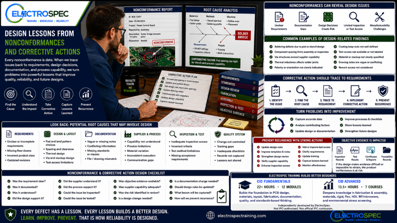
Nonconformances are often treated as manufacturing problems.
A solder defect appears.
A fabricated board has an issue.
An inspector rejects an assembly.
A supplier asks for a deviation.
A test failure occurs.
A customer reports an escape.
The immediate focus is usually containment, repair, disposition, and delivery.
That is understandable.
But there is another question designers should ask:
What is this nonconformance teaching us about the design?
A nonconformance may be caused by workmanship, process control, supplier capability, material variation, or inspection error.
But it may also point back to design decisions, documentation gaps, unclear requirements, poor manufacturability, weak inspection access, inadequate test access, or missing standards traceability.
That makes nonconformances valuable design feedback.
Defects Are Data
A defect is not only a problem.
It is data.
It tells the organization that something in the system did not work as intended.
That system may include:
- requirements
- design decisions
- materials
- supplier capability
- fabrication process
- assembly process
- inspection method
- test method
- documentation
- training
- process control
- communication
If a defect is corrected only at the product level, the organization may miss the deeper lesson.
The part may be repaired, but the cause may remain.
A stronger organization asks what the defect reveals about the design and process.
Not Every Nonconformance Is a Design Problem
Designers should not assume every defect is their fault.
A solder defect may come from process control.
A plating defect may come from fabrication.
A missing component may come from assembly execution.
A failed test may come from handling damage.
A documentation error may come from configuration control.
But designers should still participate in the learning loop.
The question is not, “Who do we blame?”
The better question is, “What allowed this problem to happen, and what can we improve?”
Sometimes the answer is process control.
Sometimes it is supplier capability.
Sometimes it is training.
Sometimes it is inspection.
Sometimes it is design.
Corrective Action Should Trace Back to Requirements
A corrective action should not stop at the symptom.
It should trace the issue back to the requirement system.
The team should ask:
- What requirement was not met?
- Where did that requirement come from?
- Was it clearly documented?
- Was it understood by the supplier or production team?
- Did the design support the requirement?
- Did the process support the requirement?
- Could the issue be inspected?
- Could the issue be tested?
- Was objective evidence available?
- Was the requirement realistic for the selected supplier and process?
This turns corrective action from paperwork into engineering learning.
Design Decisions Can Create Manufacturing Risk
Many production issues begin in design, even when they appear during manufacturing.
Examples include:
- pads that make solder joint formation difficult
- dense component placement that limits inspection access
- poor thermal relief that affects soldering
- via structures that challenge fabrication capability
- material selections that complicate processing
- missing test access
- hidden polarity markings
- coating keep-outs that are unclear
- cleaning access that is poor
- rework access that was not considered
- stackups that push supplier capability
The operator or supplier may see the defect first.
But the design may have created the conditions.
Documentation Gaps Create Nonconformances
A nonconformance may occur because the product was built incorrectly.
But sometimes it was built incorrectly because the documentation was unclear.
Documentation gaps may include:
- vague standards callouts
- missing product class
- outdated revision references
- unclear material requirements
- incomplete fabrication notes
- unclear assembly notes
- missing coating instructions
- missing cleaning requirements
- incomplete inspection criteria
- missing test requirements
- ambiguous polarity or orientation
- conflicting drawings and digital files
When documentation is unclear, suppliers and production teams may guess.
Guessing creates variation.
Variation creates risk.
Supplier Findings Should Feed Back Into Design
Supplier findings are useful.
A fabricator may report that a via structure is difficult to build.
An assembler may report repeated solder bridging.
An inspector may report limited visibility.
A test team may report poor access.
A coating supplier may report unclear masking requirements.
Those findings should not disappear after one job is complete.
They should feed back into:
- design rules
- drawing templates
- release checklists
- supplier capability reviews
- design review questions
- training materials
- future layouts
A supplier finding becomes valuable when it improves the next design.
Rework Is Also Feedback
Rework is sometimes normalized.
A team may say, “We can fix that in production.”
That mindset can be dangerous.
Rework consumes time, cost, labor, and risk.
It can also affect reliability, especially for high-reliability products.
Repeated rework should trigger design review.
The team should ask:
- Why is rework needed?
- Is the design difficult to build?
- Is the assembly process appropriate?
- Is component spacing adequate?
- Is thermal balance acceptable?
- Is inspection access clear?
- Is the documentation complete?
- Is the supplier capable?
- Is the rework allowed by requirement?
- Does rework affect qualification or reliability?
If rework is frequent, the design system may need improvement.
Escapes Require Design-Level Learning
An escape is a defect that reaches the customer or field.
Escapes are serious because they show that the design, manufacturing, inspection, test, and quality system failed to detect or prevent the issue before delivery.
When an escape occurs, the team should ask:
- Was the requirement clear?
- Did the design support the requirement?
- Was the defect detectable?
- Was inspection access adequate?
- Was the test method capable?
- Were acceptance criteria clear?
- Was objective evidence reviewed?
- Was supplier capability understood?
- Was the risk considered during design review?
- Should the design be changed?
Escapes should not only produce corrective action.
They should produce design learning.
Root Cause Analysis Should Include Design
Root cause analysis often focuses on manufacturing process causes.
That is important.
But design should also be considered.
Possible design-related contributors include:
- inadequate design rules
- unclear documentation
- poor land pattern selection
- insufficient spacing
- inadequate test access
- limited inspection access
- material mismatch
- stackup weakness
- via reliability risk
- component support concerns
- environmental stress not considered
- supplier capability not reviewed
- qualification requirements not flowed down
If design is not considered, the root cause analysis may be incomplete.
Standards Traceability Helps Find the Cause
Traceability helps the team understand what went wrong.
A nonconformance should be traceable to a requirement source.
That source may be:
- customer drawing
- contract requirement
- IPC standard
- product class
- NASA requirement
- ESA requirement
- military specification
- material requirement
- fabrication requirement
- assembly requirement
- inspection criterion
- test requirement
- qualification plan
- internal design rule
- supplier capability
When the source is known, the team can determine whether the issue was caused by a bad requirement, missing requirement, unclear requirement, poor implementation, process failure, inspection gap, or documentation problem.
Without traceability, corrective action can become guesswork.
Corrective Actions Should Improve the Design System
A corrective action should do more than fix one part.
It should improve the system.
Design-related corrective actions may include:
- update design rules
- revise drawing notes
- improve release package templates
- add supplier review requirements
- change material selection rules
- improve stackup review
- update land pattern guidance
- add inspection access checks
- add test access requirements
- improve coating documentation
- improve design review checklists
- update training
- document lessons learned
The goal is to prevent recurrence.
That means the lesson must be captured where future designers can use it.
CID Builds the Foundation for Better Root Cause Thinking
ElectroSpec’s CID Fundamentals course helps designers understand how PCB design decisions affect fabrication, assembly, inspection, documentation, and reliability.
The course includes 22+ hours of on-demand training across 12 structured modules covering materials, layout principles, mechanical and electrical considerations, thermal management, component technologies, interconnections, fabrication requirements, documentation, quality assurance, manufacturability, and standards-based design thinking.
That foundation helps designers participate more effectively in corrective actions.
A designer who understands the full product lifecycle can better recognize when a defect has design involvement.
CID Advanced Builds the Reliability Feedback Loop
ElectroSpec CID Advanced expands into areas where nonconformances can become technically complex.
The advanced track includes:
- PCB Fabrication & Assembly
- PCB Materials
- Rigid PCB Design
- Flexible PCB Design
- HDI PCB Design
- RF/Microwave PCB Design
- Environmental Stress Screening
These topics help designers understand advanced failure contributors.
A flex failure may relate to bend design, materials, or transition zones.
An HDI failure may relate to microvia reliability or supplier capability.
An RF failure may relate to stackup, dielectric material, impedance, or fabrication tolerance.
An environmental failure may relate to shock, vibration, thermal cycling, humidity, coating, or qualification planning.
Advanced corrective action requires advanced design understanding.
A Practical Corrective Action Design Checklist
When reviewing a nonconformance, ask:
- What requirement was not met?
- Where did the requirement come from?
- Was the requirement clearly documented?
- Did the design support the requirement?
- Did supplier capability support the requirement?
- Did manufacturing have clear instructions?
- Could inspection detect the issue?
- Could test detect the issue?
- Was objective evidence required and available?
- Was the issue considered during design review?
- Is a design change needed?
- Is a documentation change needed?
- Should design rules or checklists be updated?
- What lesson should be captured for future designs?
These questions help turn a defect into design improvement.
A Nonconformance Should Leave a Lesson
The worst outcome is not simply having a nonconformance.
The worst outcome is having the same nonconformance again because nothing was learned.
Every meaningful nonconformance should leave a lesson.
That lesson may improve a design rule.
It may improve a release package.
It may improve a supplier review.
It may improve inspection access.
It may improve test planning.
It may improve training.
It may improve customer communication.
When lessons are captured, the organization becomes stronger.
Independently Developed by ElectroSpec
ElectroSpec’s CID and CID Advanced courses are independently developed by ElectroSpec.
They are not IPC-authorized training and they are not official IPC curriculum.
ElectroSpec developed these courses to provide practical, standards-connected, manufacturing-aware design training for students preparing for CID and CID+ certification.
The focus is not only on creating PCB layouts.
The focus is on helping designers understand how requirements, standards, manufacturing, inspection, test, quality, reliability, and corrective action connect.
Final Thought
Nonconformances are not only quality events.
They are learning opportunities.
Defects, supplier findings, rework, test failures, escapes, and corrective actions can teach designers where requirements were unclear, where documentation was weak, where the design challenged manufacturing, where inspection or test access was inadequate, or where supplier capability was misunderstood.
A strong designer does not ignore corrective action.
A strong designer learns from it.
The best PCB design organizations do not only fix problems.
They trace them, learn from them, and prevent them from returning.
Related ElectroSpec Training
ElectroSpec’s CID Fundamentals course provides 22+ hours of on-demand PCB design training across 12 structured modules.
ElectroSpec’s CID Advanced training expands into PCB Fabrication & Assembly, PCB Materials, Rigid PCB Design, Flexible PCB Design, HDI PCB Design, RF/Microwave PCB Design, and Environmental Stress Screening.
Together, these courses help designers build the standards-connected foundation needed for CID and CID+ certification preparation.
Coming Next
The Designer’s Role in Objective Evidence
In the next article, we will discuss why objective evidence is not only a quality function, and how design decisions affect what records, tests, inspections, and documentation can prove product conformance.
IPC CID Certification — ElectroSpec
IPC CID+ Certification — ElectroSpec
IPC CID/CID+ Bundle — Complete PCB Design Certification — ElectroSpec