Designing for Qualification: Shock, Vibration, Thermal, Humidity, and Real-World Use
Jul 31, 2026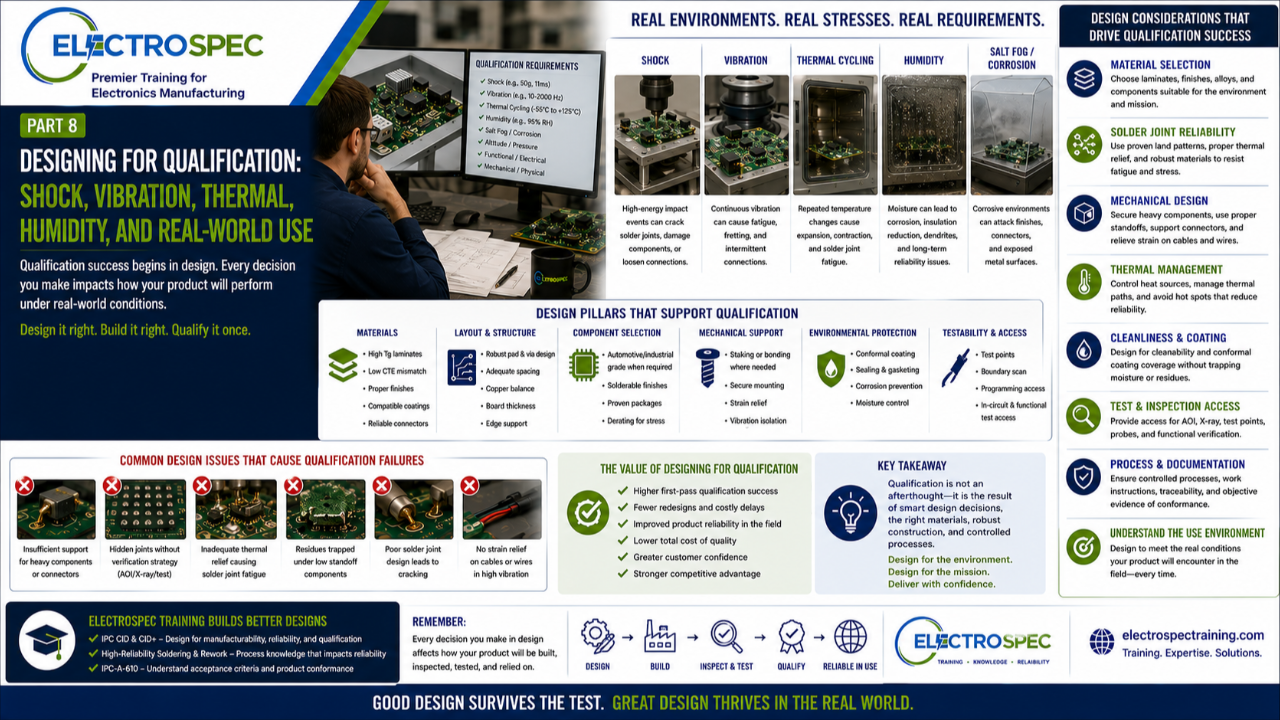
In the previous article, we discussed designing for inspection.
The main point was simple:
If you cannot inspect it, test it, or otherwise verify it, you may not be able to confidently accept it.
Now we move to an even larger design responsibility.
Qualification.
Many companies think qualification happens at the end of development.
The product is designed.
The board is built.
The assembly is inspected.
Then it is sent to qualification testing.
But qualification success does not begin in the test lab.
It begins in design.
Qualification Is Not Added at the End
Qualification testing may occur near the end of development, but the ability to pass qualification is created much earlier.
Design decisions influence whether the product can survive:
- shock
- vibration
- thermal cycling
- humidity
- contamination
- corrosion
- mechanical stress
- electrical stress
- handling
- transportation
- storage
- long-term service conditions
If the design does not account for the real environment, the product may fail even if it was built exactly to the drawing.
That is why designers must understand the qualification requirements before layout decisions are finalized.
Real-World Use Drives Design Requirements
A product used in a consumer device may have very different requirements than a product used in aerospace, defense, medical, transportation, energy, or industrial infrastructure.
The end-use environment affects almost everything.
A high-reliability electronic product may need to withstand:
- launch vibration
- aircraft vibration
- vehicle shock
- repeated thermal cycling
- humidity exposure
- salt atmosphere
- high altitude
- enclosure heating
- connector strain
- cable movement
- field handling
- long storage time
- mission-critical operation
The designer must understand what the product is expected to survive.
A design that is acceptable for one environment may be unacceptable for another.
Material Selection Matters
Material choices affect qualification performance.
Designers should consider:
- laminate material
- glass transition temperature
- coefficient of thermal expansion
- copper weight
- board thickness
- solder mask
- surface finish
- component finish
- solder alloy
- adhesive materials
- staking compounds
- conformal coating
- underfill where applicable
- connector materials
- wire insulation
- cable jacket materials
- hardware materials
Materials are not selected only for cost or availability.
They must support manufacturing, assembly, inspection, qualification, and field performance.
A poor material choice can create solderability problems, thermal stress, cracking, corrosion risk, coating issues, or long-term reliability concerns.
Thermal Cycling Challenges the Design
Thermal cycling can be one of the most important qualification stresses for electronics.
Repeated heating and cooling can strain solder joints, component terminations, vias, plated through-holes, connectors, coatings, and mechanical interfaces.
Designers should consider:
- component package selection
- CTE mismatch
- board material
- solder joint geometry
- component size
- thermal mass
- via structure
- plated through-hole reliability
- connector mounting
- mechanical support
- underfill or staking where appropriate
- thermal relief
- heat dissipation
- hot spots
A solder joint may pass visual inspection after assembly but still be vulnerable to fatigue during thermal cycling.
Qualification exposes weaknesses that may not be obvious during normal inspection.
Shock and Vibration Require Mechanical Thinking
Electronic assemblies are mechanical systems too.
Shock and vibration can damage components, solder joints, connectors, wires, hardware, and board structures.
Designers should consider:
- component mass
- component location
- board support
- mounting hole locations
- stiffeners
- connector retention
- wire strain relief
- cable routing
- staking or bonding
- hardware locking features
- resonance
- enclosure design
- edge support
- clearance
- fastener selection
Large or heavy components may need additional mechanical support.
Connectors may need strain relief.
Cables may need routing control.
Boards may need support to prevent flexure.
A design that ignores mechanical loading may fail during vibration even if the circuit works perfectly on the bench.
Humidity and Contamination Affect Reliability
Humidity, residues, ionic contamination, flux chemistry, cleaning effectiveness, and material compatibility can all affect reliability.
Designers should consider:
- component spacing
- surface insulation resistance
- cleanliness requirements
- flux compatibility
- cleaning access
- residue entrapment
- conformal coating coverage
- coating keep-outs
- moisture-sensitive components
- corrosion-sensitive materials
- enclosure sealing
- condensation risk
- voltage spacing
- leakage paths
A design that traps residue under low-standoff components may create risk.
A design that makes cleaning or coating difficult may create qualification or long-term reliability problems.
This is why design, process engineering, and quality engineering must work together.
Conformal Coating Is Not a Magic Fix
Conformal coating can protect electronics from moisture, contamination, and environmental exposure.
But coating does not fix a poor design.
Designers must consider:
- coating material selection
- coating coverage
- masking requirements
- component compatibility
- connector keep-outs
- test point access
- inspection of coating
- coating thickness
- cure requirements
- rework after coating
- trapped residues
- sharp edges
- spacing under components
A coating process must be designed into the product and manufacturing flow.
It should not be treated as an afterthought.
Solder Joint Reliability Is Part of Qualification
Qualification failures are often tied back to interconnect reliability.
Solder joints are affected by design choices such as:
- pad geometry
- component termination geometry
- package size
- thermal mass
- board finish
- component finish
- solder alloy
- stencil design
- reflow profile
- through-hole design
- lead protrusion
- mechanical support
- underfill or staking
- vibration exposure
- thermal cycling exposure
A solder joint is not just a workmanship feature.
It is a reliability feature.
Designers must understand how their decisions influence both the initial solder joint and the long-term performance of that joint.
Qualification Requires Process Control
Even the best design can fail if the manufacturing process is not controlled.
Qualification success depends on the connection between design and process.
That may include:
- controlled soldering processes
- controlled cleaning processes
- controlled coating processes
- controlled crimping processes
- controlled torque processes
- controlled materials
- controlled tooling
- documented work instructions
- inspection criteria
- test procedures
- traceability
- configuration control
Qualification does not only test the design.
It also tests whether the manufacturing system can repeatedly produce the design correctly.
Designers Should Review Qualification Requirements Early
Designers should not wait until test planning to think about qualification.
They should review qualification requirements during:
- requirements development
- material selection
- stackup definition
- component selection
- layout
- design review
- manufacturing review
- inspection planning
- test planning
- supplier selection
The earlier qualification risks are addressed, the easier they are to reduce.
Once hardware is built, design changes become slower, more expensive, and more disruptive.
Design Reviews Should Include Qualification Thinking
A strong design review should ask:
- What environment must this product survive?
- What qualification tests apply?
- What failure modes are most likely?
- Are materials appropriate for the environment?
- Are solder joints mechanically and thermally robust?
- Are heavy components supported?
- Are connectors strain relieved?
- Can the product be cleaned, coated, inspected, and tested?
- Are there trapped residues or moisture risks?
- Are thermal paths understood?
- Are shock and vibration loads addressed?
- Is the design manufacturable using the intended process?
- Is there objective evidence that the design can meet the requirement?
These questions help prevent qualification failures.
Qualification Failure Is Expensive
Qualification failures can be costly.
They may cause:
- redesign
- schedule delay
- additional testing
- customer concern
- production interruption
- material changes
- process changes
- supplier changes
- rework
- scrap
- contract risk
A qualification failure is not just a test result.
It is evidence that the design, manufacturing process, or requirement interpretation may need correction.
Preventing qualification failure begins with better design decisions.
Final Thought
Qualification success is designed into the product.
It is not added at the end.
Designers must understand the environment, select appropriate materials, consider mechanical and thermal stresses, support reliable solder joints, plan for cleaning and coating, and ensure the product can be manufactured, inspected, tested, and verified.
A good design is not only electrically correct.
It is manufacturable.
It is inspectable.
It is acceptable.
It is qualifiable.
And most importantly, it is capable of surviving the real world where the customer will use it.
Related ElectroSpec Training
ElectroSpec’s IPC CID and CID+ training programs help PCB designers and product engineers understand how design decisions affect manufacturability, reliability, inspection, qualification, and long-term product performance.
ElectroSpec’s High-Reliability Soldering & Rework training helps engineering and manufacturing teams understand how soldering processes, workmanship expectations, materials, and reliability concerns connect to product performance.
Coming Next
Why Designers, Process Engineers, and Inspectors Must Talk Before Production
In the next article, we will discuss why design, process engineering, manufacturing engineering, quality, and inspection teams must collaborate before production begins—and how early communication prevents costly manufacturing and reliability problems.