The Release Package: Where Design Intent Becomes Manufacturing Instruction
Aug 29, 2026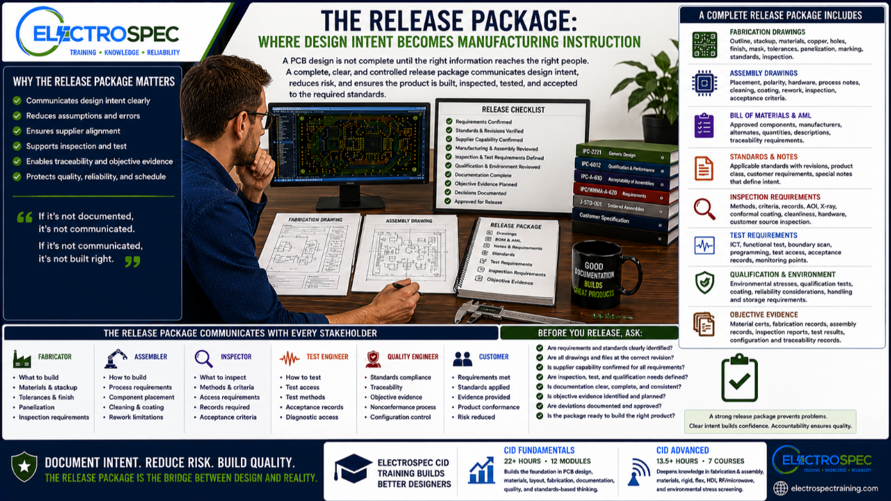
A PCB design is not finished when the layout is routed.
It is not finished when the schematic is complete.
It is not finished when the design rule check passes.
It is not even finished when the design review is complete.
The design becomes real when the release package clearly communicates the designer’s intent to fabrication, assembly, inspection, test, quality, and the customer.
That release package is where design intent becomes manufacturing instruction.
If the package is incomplete, unclear, outdated, contradictory, or missing key requirements, even a strong design can be built incorrectly.
The Release Package Is the Handoff
The release package is the handoff from engineering to the people who must build and verify the product.
That may include:
- PCB fabricator
- assembly supplier
- process engineer
- manufacturing engineer
- inspector
- test engineer
- quality engineer
- customer reviewer
- auditor
- configuration manager
Each group depends on the release package to understand what must be built, how it must be built, what standards apply, what inspection is required, what test evidence is needed, and what records must be maintained.
A clear release package reduces assumptions.
A weak release package creates risk.
A Good Layout Can Fail Through Poor Documentation
Designers sometimes focus heavily on layout quality, but documentation quality matters just as much.
A good layout can still create problems if the release package fails to define:
- material requirements
- stackup
- copper weights
- surface finish
- solder mask
- controlled impedance
- hole requirements
- tolerances
- product class
- standards and revisions
- assembly requirements
- cleaning requirements
- coating requirements
- inspection requirements
- test requirements
- qualification requirements
- objective evidence
If the design intent is not documented, the supplier may have to guess.
Guessing is not engineering.
Fabrication Drawings Define the Bare Board
The fabrication drawing tells the board supplier what must be fabricated.
It should communicate the bare board requirements clearly and completely.
Depending on the product, the fabrication drawing may address:
- board outline
- dimensions
- tolerances
- layer stackup
- laminate materials
- copper thickness
- hole sizes
- plated and non-plated holes
- via requirements
- annular ring expectations
- controlled impedance
- solder mask
- legend
- surface finish
- panelization requirements
- bow and twist
- marking
- inspection requirements
- applicable standards
- product class
- special customer requirements
The bare board is the foundation of the assembly.
If the fabrication package is unclear, the assembly begins with risk.
Assembly Drawings Communicate Build Intent
The assembly drawing tells the assembler how the product must be built.
It should communicate what goes where, what standards apply, what process expectations matter, and what special handling or inspection requirements are needed.
Assembly documentation may include:
- component placement
- polarity
- orientation
- hardware installation
- connector installation
- soldering requirements
- special process notes
- cleaning requirements
- conformal coating requirements
- staking or bonding requirements
- rework limitations
- inspection criteria
- acceptance class
- test requirements
- serialization
- labels and markings
- torque requirements
- handling cautions
The assembly drawing should not assume the assembler knows the designer’s intent.
It should clearly state what matters.
The Bill of Materials Must Match the Design Intent
The bill of materials is not just a purchasing list.
It is part of the technical requirement package.
The BOM helps define the approved components, materials, alternates, manufacturer part numbers, descriptions, reference designators, quantities, and sometimes approved manufacturer information.
For high-reliability products, the BOM may also connect to:
- approved manufacturer lists
- approved vendor lists
- material restrictions
- component qualifications
- traceability requirements
- lifecycle concerns
- counterfeit avoidance
- substitutions
- customer approvals
A substitution that appears minor to purchasing may be significant to design, assembly, reliability, or customer compliance.
That is why the BOM must be controlled.
Standards Callouts Must Be Specific
A vague standards note can create confusion.
A release package should identify the applicable standards, revisions, product class, and any customer-specific additions or restrictions.
A weak note might say, “Build to IPC.”
That is not enough.
The package should clarify what is being invoked.
For example, design requirements, bare board acceptability, assembly process requirements, assembly acceptability, coating, solderability, cleanliness, inspection, or customer-specific requirements may each involve different standards or specifications.
The release package should make the requirement clear.
A standard title without context is not a complete instruction.
Notes Should Reduce Ambiguity, Not Create It
Drawing notes are powerful.
They can define requirements, but they can also create confusion if they are vague, outdated, copied from another product, or inconsistent with the design.
Good notes should be:
- clear
- current
- applicable
- traceable
- nonconflicting
- measurable when possible
- aligned with the design
- aligned with supplier capability
- aligned with customer requirements
Copied notes can be dangerous.
A note that made sense on one product may not apply to another product.
Every note should earn its place in the release package.
Inspection Requirements Must Be Communicated
Inspection should not rely on assumption.
If the product requires specific inspection methods or acceptance criteria, the release package should identify them.
This may include:
- bare board inspection
- assembly inspection
- visual inspection
- automated optical inspection
- X-ray inspection
- dimensional inspection
- coating inspection
- cleanliness verification
- hardware inspection
- solder joint inspection
- marking and labeling verification
- customer source inspection
- special inspection records
Inspection requirements must be planned before production.
If the supplier cannot inspect what the package requires, that problem should be resolved before release.
Test Requirements Must Be Defined
Test requirements should also be part of the release package when applicable.
That may include:
- in-circuit test
- functional test
- programming
- boundary scan
- continuity testing
- insulation resistance testing
- high-potential testing
- environmental test monitoring
- qualification testing
- acceptance test records
- customer test reports
A test requirement that is not communicated may not be performed.
A test method that lacks access may not be possible.
The release package should align design intent, test access, test method, and evidence.
Coating, Cleaning, and Special Processes Need Clear Instructions
Cleaning and coating are common sources of confusion.
If the product requires cleaning, coating, staking, bonding, potting, masking, or other special processes, the release package should define the requirement clearly.
Important details may include:
- materials
- approved processes
- application areas
- keep-out areas
- masking requirements
- thickness expectations
- inspection method
- cure requirements
- cleanliness requirements
- rework limitations
- records required
A conformal coating note is not enough if the product has connectors, test points, thermal areas, keep-outs, or inspection requirements that must be protected.
Special processes must be designed and documented.
Objective Evidence Should Be Planned in the Package
For high-reliability products, the release package should help define objective evidence.
Evidence may include:
- material certifications
- fabrication records
- assembly records
- inspection reports
- test results
- qualification reports
- process control records
- configuration records
- traceability records
- deviation approvals
- nonconformance records
The team should know what records are required before the build begins.
If the evidence is needed at delivery, it must be planned at release.
Revision Control Protects the Product
Release packages must be controlled.
If drawings, files, BOMs, standards notes, test requirements, or assembly instructions are not under proper revision control, the supplier may build the wrong product.
Revision control should address:
- schematic revision
- PCB layout revision
- fabrication drawing revision
- assembly drawing revision
- BOM revision
- approved manufacturer list revision
- test procedure revision
- drawing notes
- customer changes
- engineering change notices
- deviation approvals
A released design is a controlled technical baseline.
The release package should protect that baseline.
Digital Outputs Must Match the Drawings
Modern PCB release packages may include Gerbers, drill files, ODB++, IPC-2581, pick-and-place files, netlists, centroid data, 3D models, drawings, BOMs, and test documentation.
Those files must agree.
If the digital data conflicts with the drawing, the supplier may not know which source controls.
The design team should verify that:
- output files match the released layout
- stackup matches the drawing
- drill files match the hole table
- BOM matches the assembly drawing
- placement files match the assembly revision
- controlled impedance notes match the stackup
- special process notes match the actual product
- test requirements match the test access
- standards callouts are current and correct
The release package should tell one consistent story.
Supplier Questions Are Feedback
Supplier questions are not automatically a problem.
They can be valuable feedback.
But repeated supplier questions may indicate that the release package is unclear.
Common supplier questions may involve:
- material substitutions
- stackup clarification
- impedance tolerance
- surface finish
- solder mask clearance
- hole tolerances
- via requirements
- panelization
- assembly polarity
- coating keep-outs
- cleaning requirements
- inspection expectations
- test records
- conflicting notes
When suppliers ask the same questions repeatedly, the design package should improve.
Good organizations use supplier feedback to strengthen future releases.
CID Builds Documentation Discipline
ElectroSpec’s CID Fundamentals course helps designers understand the importance of documentation as part of the PCB design process.
The course includes 22+ hours of on-demand training across 12 structured modules covering materials, layout principles, mechanical and electrical considerations, thermal management, component technologies, interconnections, fabrication requirements, documentation, quality assurance, manufacturability, and standards-based design thinking.
Documentation is not an afterthought.
It is how the design intent becomes build instruction.
CID Advanced Builds the Advanced Release Mindset
ElectroSpec CID Advanced expands the discussion into advanced design areas, including:
- PCB Fabrication & Assembly
- PCB Materials
- Rigid PCB Design
- Flexible PCB Design
- HDI PCB Design
- RF/Microwave PCB Design
- Environmental Stress Screening
Advanced products require stronger release discipline.
Flex designs need bend, material, stiffener, and transition requirements.
HDI designs need via structure, stackup, supplier capability, and reliability clarity.
RF designs need material, impedance, stackup, copper, and fabrication control.
Harsh-environment designs need qualification, coating, cleaning, inspection, and evidence planning.
The more advanced the design, the more important the release package becomes.
A Practical Release Package Checklist
Before release, ask:
- Are the correct drawings included?
- Are all files at the correct revision?
- Is the BOM complete and controlled?
- Are standards and revisions clearly identified?
- Is product class defined?
- Are material requirements clear?
- Is the stackup complete?
- Are controlled impedance requirements defined?
- Are fabrication tolerances clear?
- Are assembly requirements clear?
- Are cleaning and coating requirements defined?
- Are inspection requirements identified?
- Are test requirements identified?
- Are qualification requirements included?
- Are records and objective evidence requirements defined?
- Are deviations documented and approved?
- Do all files agree with each other?
This checklist helps prevent avoidable manufacturing confusion.
Independently Developed by ElectroSpec
ElectroSpec’s CID and CID Advanced courses are independently developed by ElectroSpec.
They are not IPC-authorized training and they are not official IPC curriculum.
ElectroSpec developed these courses to provide practical, standards-connected, manufacturing-aware design training for students preparing for CID and CID+ certification.
The focus is not only on designing the layout.
The focus is on communicating the full design intent so the product can be built, inspected, tested, accepted, and trusted.
Final Thought
The release package is where engineering intent becomes manufacturing instruction.
It tells the fabricator what to build.
It tells the assembler how to build it.
It tells inspection what to verify.
It tells test what to prove.
It tells quality what evidence to collect.
It tells the customer what was delivered.
A good PCB design deserves a good release package.
Without clear documentation, even a strong design can fail in execution.
The layout creates the product concept.
The release package makes the product buildable.
Related ElectroSpec Training
ElectroSpec’s CID Fundamentals course provides 22+ hours of on-demand PCB design training across 12 structured modules.
ElectroSpec’s CID Advanced training expands into PCB Fabrication & Assembly, PCB Materials, Rigid PCB Design, Flexible PCB Design, HDI PCB Design, RF/Microwave PCB Design, and Environmental Stress Screening.
Together, these courses help designers build the standards-connected foundation needed for CID and CID+ certification preparation.
Coming Next
Supplier Questions Are Design Feedback
In the next article, we will discuss why fabrication and assembly supplier questions should not be treated as interruptions, but as valuable signals about unclear requirements, missing documentation, manufacturability risk, and opportunities to improve future designs.
IPC CID Certification — ElectroSpec
IPC CID+ Certification — ElectroSpec
IPC CID/CID+ Bundle — Complete PCB Design Certification — ElectroSpec