Documentation and Release Packages: Communicating Design Intent
Sep 24, 2026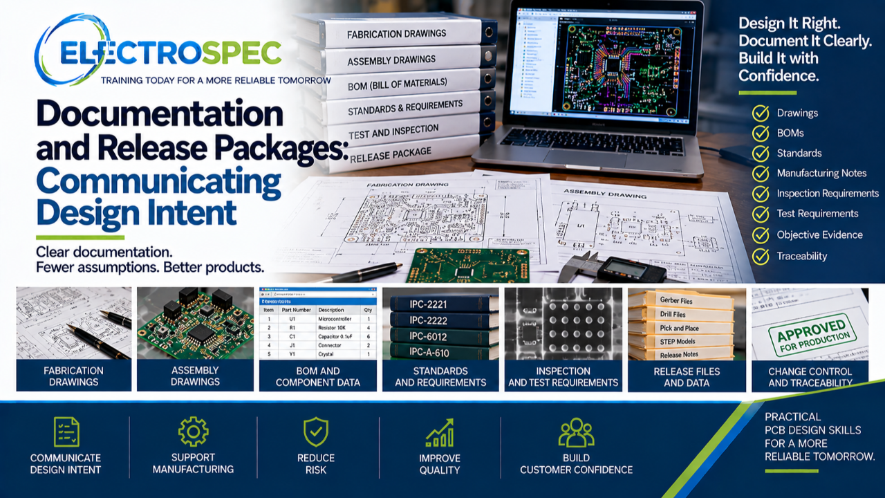
A PCB design is not complete when the layout is routed.
It is complete when the design intent is communicated clearly enough for the product to be fabricated, assembled, inspected, tested, documented, and accepted.
That communication happens through documentation and the release package.
A good release package reduces assumptions.
A weak release package creates risk.
Documentation Turns Intent Into Instruction
Designers may understand why they made a decision, but suppliers cannot build from hidden intent.
The release package must explain what is required.
That may include fabrication drawings, assembly drawings, BOMs, stackup, notes, material requirements, surface finish, solder mask, controlled impedance, inspection requirements, test requirements, and special processes.
If the requirement is not documented, it may not be implemented.
Fabrication Drawings Define the Bare Board
The fabrication drawing communicates what the board supplier must build.
It may define board outline, dimensions, tolerances, stackup, materials, copper thickness, hole sizes, plated and non-plated holes, surface finish, solder mask, legend, controlled impedance, inspection requirements, product class, and standards.
The bare board is the foundation of the assembly.
The fabrication drawing must be clear.
Assembly Drawings Define the Build
The assembly drawing communicates how components, hardware, connectors, labels, coatings, and other features are installed.
It should support orientation, polarity, component placement, soldering expectations, cleaning, coating, staking, bonding, inspection, test, rework limitations, and acceptance criteria.
A good assembly drawing reduces interpretation.
The BOM Must Be Controlled
The bill of materials is part of the technical package.
It should define approved components, manufacturers, quantities, descriptions, reference designators, alternates, and restrictions when applicable.
A substitution can affect fit, function, solderability, thermal behavior, reliability, qualification, or customer approval.
The BOM must match the design intent.
Standards Callouts Must Be Clear
A vague note such as “build to IPC” is usually not enough.
The release package should clearly identify applicable standards, revisions, product class, and customer-specific requirements.
Designers should define what applies to fabrication, assembly, inspection, test, coating, cleaning, and evidence.
Standards callouts should reduce ambiguity, not create it.
Digital Files Must Agree
Modern release packages may include Gerbers, drill files, ODB++, IPC-2581, pick-and-place data, netlists, centroid files, drawings, BOMs, models, and test documents.
These files must agree with each other.
If the drawing says one thing and the digital output says another, the supplier may not know what controls.
The release package should tell one consistent story.
Inspection and Test Requirements Must Be Included
Inspection and test should not be assumed.
If the product requires visual inspection, X-ray, AOI, dimensional inspection, coating inspection, cleanliness verification, ICT, functional test, programming, boundary scan, or qualification testing, those requirements should be communicated.
Evidence needed at delivery must be planned before production.
Documentation Supports Objective Evidence
Objective evidence depends on clear requirements.
Material certifications, fabrication records, assembly records, inspection reports, test results, qualification data, and traceability records must connect back to the released design.
A clear release package makes evidence easier to collect and easier to review.
CID Builds Documentation Discipline
ElectroSpec’s CID Fundamentals course includes documentation because designers need to understand how design intent becomes manufacturing instruction.
The course provides 22+ hours of self-paced, on-demand PCB design training across 12 structured modules covering materials, layout principles, mechanical and electrical considerations, thermal management, component technologies, interconnections, fabrication requirements, documentation, quality assurance, manufacturability, and standards-based design thinking.
Final Thought
A strong layout deserves strong documentation.
The release package tells the fabricator what to build, the assembler how to build it, inspection what to verify, test what to prove, quality what evidence to collect, and the customer what was delivered.
Good documentation protects the product.
Related ElectroSpec Training
ElectroSpec’s CID Fundamentals course provides 22+ hours of self-paced, on-demand PCB design training across 12 structured modules.
The course helps designers build a standards-connected foundation in documentation, materials, layout, fabrication, manufacturability, quality, and design decision-making while preparing for CID certification.
Coming Next
Quality Assurance and Product Acceptance in PCB Design
In the next article, we will continue the CID Fundamentals track and discuss why quality assurance and product acceptance should influence PCB design before production begins.