Class 3 and High-Reliability Design: More Than Just a Label
Aug 21, 2026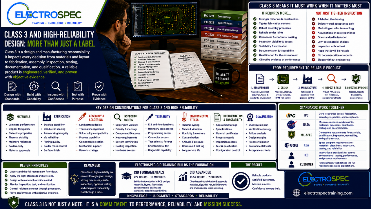
Class 3 is one of the most important concepts in high-reliability electronics.
It is often associated with products where continued performance or performance on demand is critical. These products may be used in aerospace, defense, space, medical, industrial, transportation, infrastructure, or other demanding applications.
But Class 3 should never be treated as just a phrase on a drawing.
It should not be treated as a marketing label.
It should not be treated as a slogan.
Class 3 is a design and manufacturing responsibility.
When Class 3 is invoked, the designer must understand what that means for materials, fabrication, assembly, soldering, inspection, test, documentation, process control, qualification, and objective evidence.
A product does not become high reliability because someone writes “Class 3” on a drawing.
The design must support the requirement.
The manufacturing process must support the requirement.
The inspection and test strategy must support the requirement.
The objective evidence must prove the requirement was met.
Class 3 Starts with the Requirement
Class 3 should begin with a real requirement.
That requirement may come from:
- customer drawings
- contracts
- purchase orders
- program specifications
- IPC standards
- customer flow-downs
- NASA requirements
- ESA requirements
- military specifications
- medical product requirements
- environmental qualification plans
- internal company design rules
The designer must understand where the Class 3 requirement comes from and how it applies to the product.
Class 3 is not only a final inspection category.
It affects the entire product lifecycle.
It influences how the board is designed, how the board is fabricated, how the assembly is built, how the product is inspected, how it is tested, and how conformance is documented.
Class 3 Is More Than Tighter Acceptance Criteria
A common mistake is thinking Class 3 only means tighter visual inspection criteria.
Inspection matters.
Acceptance criteria matter.
But Class 3 is broader than appearance.
Class 3 thinking should influence:
- material selection
- board construction
- conductor spacing
- annular ring
- plated through-hole reliability
- via structures
- solder joint reliability
- component selection
- thermal management
- mechanical support
- cleanliness
- coating
- inspection access
- test access
- supplier capability
- process control
- documentation
- qualification planning
If the design does not support Class 3 expectations, inspection alone cannot fix the problem.
Inspection can identify defects.
It cannot redesign the product.
High Reliability Must Be Designed In
High reliability is not added at the end.
It is created through design choices, material choices, manufacturing controls, inspection methods, test planning, qualification, and documentation.
Designers should ask:
- What failure modes matter most?
- What environment will the product see?
- What materials are appropriate?
- What fabrication risks exist?
- What assembly processes will be used?
- Can solder joints be formed consistently?
- Can the product be inspected?
- Can the product be tested?
- Can the product be reworked if allowed?
- Can the product survive shock, vibration, humidity, thermal cycling, and field use?
- What evidence will prove conformance?
These questions should be asked before the design is released.
High-reliability design begins long before final inspection.
Materials Matter More in Class 3 Products
Material selection becomes more important when reliability expectations increase.
The designer must think about how materials affect:
- dielectric performance
- thermal expansion
- glass transition behavior
- moisture absorption
- copper adhesion
- plating reliability
- solderability
- impedance stability
- dimensional stability
- cleanliness
- coating compatibility
- environmental durability
For Class 3 and high-reliability products, material decisions should be deliberate.
A material that may be acceptable for a low-risk product may not be appropriate for a harsh environment, high-temperature application, long-life product, or mission-critical system.
The designer must understand the product environment and select materials accordingly.
Fabrication Capability Matters
Class 3 design also depends on fabrication capability.
The bare printed board must be capable of supporting the reliability expectation.
Designers should consider:
- stackup
- conductor width and spacing
- copper thickness
- plated through-hole quality
- annular ring
- via structures
- solder mask registration
- surface finish
- board thickness
- bow and twist
- layer registration
- supplier capability
- inspection requirements
- documentation clarity
A design may look correct in CAD, but still create fabrication risk.
For Class 3 products, those risks matter.
A weak bare board becomes the foundation for a weak assembly.
Assembly Process Matters
Class 3 reliability also depends on assembly process capability.
Designers influence the assembly process through component selection, land pattern design, spacing, thermal relief, test access, inspection access, and documentation.
Design decisions can affect:
- solder paste printing
- component placement
- reflow soldering
- wave soldering
- selective soldering
- manual soldering
- cleaning
- conformal coating
- staking or bonding
- rework access
- inspection strategy
- test strategy
The designer does not need to become the soldering operator.
But the designer must understand how design decisions affect whether the assembly process can meet the requirement.
Good design gives manufacturing a fair chance to succeed.
Solder Joint Reliability Starts Before Soldering
Solder joints are formed during manufacturing, but many solder joint risks are created in design.
Designers influence solder joint reliability through:
- pad geometry
- component package selection
- hole-to-lead relationship
- thermal relief
- copper balance
- board thickness
- surface finish
- component finish
- mechanical support
- vibration exposure
- thermal cycling exposure
- rework limitations
A solder joint that passes visual inspection may still be at risk if the design creates mechanical stress, thermal imbalance, poor support, or fatigue sensitivity.
Class 3 design must consider reliability, not only appearance.
Inspection Access Must Be Planned
Class 3 products often require strong inspection confidence.
Designers should ask:
- Can solder joints be inspected?
- Are polarity marks visible?
- Are reference designators useful?
- Can bottom termination components be verified?
- Is X-ray inspection needed?
- Are test points accessible?
- Can coating coverage be inspected?
- Can cleanliness be verified?
- Can hardware installation be confirmed?
- Can defects be identified before delivery?
If inspection access is poor, the organization may need alternate verification methods.
Those methods should be planned before release, not discovered during production.
A design that cannot be inspected or verified with confidence creates risk.
Testability Supports High Reliability
Testing is part of the Class 3 reliability framework.
Designers should think about:
- in-circuit test access
- functional test access
- boundary scan
- programming access
- connector access
- environmental test monitoring
- failure isolation
- diagnostic capability
- acceptance test records
- qualification test records
A product that cannot be tested effectively is difficult to accept with confidence.
Testability should not be added after the layout is complete.
It should be designed into the product.
Cleanliness and Coating Cannot Be Afterthoughts
Cleanliness and coating are especially important for many high-reliability products.
Designers affect cleanliness through spacing, component density, package selection, cleaning access, flux entrapment risk, and documentation.
Designers affect coating through component placement, keep-outs, connector access, masking requirements, inspection access, and material compatibility.
A conformal coating cannot compensate for poor cleanliness, poor material compatibility, or unclear requirements.
A coating strategy should be part of the design discussion early.
Environmental Stress Changes the Design Problem
Class 3 and high-reliability products may experience demanding environments.
Those environments may include:
- thermal cycling
- shock
- vibration
- humidity
- altitude
- contamination
- corrosion
- storage
- transportation
- handling
- long service life
- operation on demand
These stresses affect solder joints, interconnects, materials, connectors, coatings, mechanical supports, and component packages.
Designers should understand the environment before selecting materials, stackups, interconnects, packages, and support methods.
A product may pass electrical test and still fail in the real world if environmental stress was not considered.
Documentation and Objective Evidence Matter
Class 3 products often require strong documentation and objective evidence.
That evidence may include:
- approved drawings
- material certifications
- fabrication records
- assembly records
- inspection records
- test results
- qualification reports
- process control records
- configuration control records
- traceability records
- nonconformance records
- deviation approvals
A design decision should be traceable.
A requirement should be verifiable.
A product acceptance decision should be supported by evidence.
For high-reliability products, documentation is not paperwork for its own sake.
It is part of the reliability system.
Standards Traceability Makes the Design Defensible
A Class 3 design decision should not be based only on habit or opinion.
The designer should be able to explain the design basis.
Was the decision based on:
- IPC design requirements?
- Class 3 expectations?
- customer drawings?
- contract flow-downs?
- NASA requirements?
- ESA requirements?
- military specifications?
- material requirements?
- fabrication capability?
- assembly process requirements?
- inspection criteria?
- qualification requirements?
- engineering judgment?
Traceability builds confidence.
It helps designers communicate with suppliers, manufacturing teams, inspectors, quality engineers, auditors, customers, and failure analysis teams.
A design decision with traceability becomes part of the engineering record.
CID Builds the Foundation for Class 3 Thinking
ElectroSpec’s CID Fundamentals course helps designers build the foundation needed for standards-based PCB design.
The course includes 22+ hours of on-demand training across 12 structured modules covering materials, layout principles, mechanical and electrical considerations, thermal management, component technologies, interconnections, fabrication requirements, documentation, quality assurance, manufacturability, and standards-based design thinking.
That foundation matters because Class 3 reliability depends on many design decisions.
Designers need to understand how those decisions affect fabrication, assembly, inspection, acceptance, and reliability.
CID Advanced Builds the High-Reliability Framework
ElectroSpec CID Advanced builds on the foundation with specialized advanced courses in:
- PCB Fabrication & Assembly
- PCB Materials
- Rigid PCB Design
- Flexible PCB Design
- HDI PCB Design
- RF/Microwave PCB Design
- Environmental Stress Screening
These topics are highly relevant to Class 3 and high-reliability products.
Advanced designers need to understand materials, fabrication capability, board technology, environmental stress, qualification risk, and reliability.
CID Advanced helps connect those topics into a practical design framework.
Class 3 Still Requires Judgment
Even with standards, the designer still needs judgment.
The designer must balance:
- reliability and cost
- density and inspection access
- performance and manufacturability
- material performance and availability
- qualification risk and schedule
- customer requirements and supplier capability
- electrical performance and mechanical durability
- documentation detail and usability
Standards provide the rules.
Designers create the solution.
Class 3 does not remove engineering judgment.
It raises the importance of it.
A Better Class 3 Design Review
A strong Class 3 design review should ask:
- What requirements are flowed down?
- What standards and revisions apply?
- What class applies?
- What customer requirements apply?
- What environment must the product survive?
- Are materials appropriate?
- Can the board be fabricated reliably?
- Can the assembly process meet the requirement?
- Can the product be inspected and tested?
- Is rework possible or prohibited?
- What qualification testing is required?
- What objective evidence will prove conformance?
- What risks need mitigation before release?
These questions help move Class 3 from a label to a real design process.
Independently Developed by ElectroSpec
ElectroSpec’s CID and CID Advanced courses are independently developed by ElectroSpec.
They are not IPC-authorized training and they are not official IPC curriculum.
ElectroSpec developed these courses to provide practical, standards-connected, manufacturing-aware design training for students preparing for CID and CID+ certification.
The focus is not simply knowing that Class 3 exists.
The focus is understanding how high-reliability requirements affect real design decisions.
Final Thought
Class 3 is not just a drawing note.
It is not just a marketing phrase.
It is not just tighter inspection.
Class 3 is a design and manufacturing responsibility.
It affects materials, fabrication, assembly, soldering, inspection, testing, documentation, process control, qualification, and objective evidence.
A reliable product is not created by a label.
It is created by requirements, standards, judgment, manufacturing capability, verification, and traceability.
Good designers understand that difference.
Related ElectroSpec Training
ElectroSpec’s CID Fundamentals course provides 22+ hours of on-demand PCB design training across 12 structured modules.
ElectroSpec’s CID Advanced training expands into PCB Fabrication & Assembly, PCB Materials, Rigid PCB Design, Flexible PCB Design, HDI PCB Design, RF/Microwave PCB Design, and Environmental Stress Screening.
Together, these courses help designers build the standards-connected foundation needed for CID and CID+ certification preparation.
Coming Next
Designing for Environmental Stress, Qualification, and Harsh Environments
In the next article, we will discuss why shock, vibration, thermal cycling, humidity, contamination, and qualification requirements must influence PCB design before the product is built.
IPC CID Certification — ElectroSpec
IPC CID+ Certification — ElectroSpec
IPC CID/CID+ Bundle — Complete PCB Design Certification — ElectroSpec