The Designer’s Role in Objective Evidence
Sep 01, 2026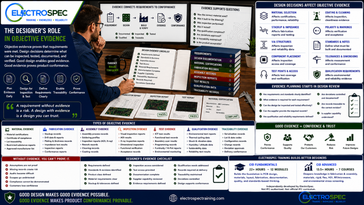
Objective evidence is often treated as a quality function.
Inspection records.
Test reports.
Material certifications.
Fabrication records.
Assembly records.
Qualification data.
Traceability records.
Those records may be collected by quality, manufacturing, test, or suppliers.
But designers have a major role in whether objective evidence can be created in the first place.
A designer may not write every inspection report.
A designer may not run every test.
A designer may not collect every certificate.
But design decisions determine what can be inspected, what can be tested, what can be documented, what can be verified, and what can be proven.
That is why objective evidence begins earlier than many people think.
It begins in design.
Objective Evidence Proves the Requirement Was Met
Objective evidence is the record that shows a requirement was satisfied.
It may answer questions such as:
- Was the correct material used?
- Was the board fabricated to the drawing?
- Was the assembly built to the required class?
- Was inspection performed?
- Was the product tested?
- Was qualification completed?
- Were deviations approved?
- Was traceability maintained?
- Was the product accepted based on evidence?
For high-reliability electronics, objective evidence is not paperwork for its own sake.
It is how the organization proves conformance.
Without evidence, teams may believe the product is acceptable, but belief is not proof.
Design Decisions Affect Evidence
A designer affects objective evidence through many choices.
For example:
A material selection affects what certifications may be required.
A stackup affects fabrication records and impedance verification.
A via structure affects inspection and reliability evidence.
A component placement affects visual inspection access.
A bottom termination component affects X-ray or alternate verification needs.
A test point decision affects test coverage.
A coating requirement affects inspection records.
A qualification requirement affects environmental test evidence.
A drawing note affects what the supplier must build and document.
Design decisions create evidence needs.
If evidence is needed later, the design must support it now.
The Drawing Package Defines Much of the Evidence
The release package often defines what evidence must be generated.
Drawings, notes, specifications, standards callouts, test requirements, inspection requirements, and qualification requirements help establish what records are needed.
A drawing package may require:
- material certification
- controlled impedance reports
- bare board inspection records
- solderability evidence
- assembly inspection records
- cleanliness evidence
- coating inspection records
- functional test results
- environmental test results
- qualification reports
- serialization records
- lot traceability
- deviation approvals
If the designer does not define the requirement clearly, the supplier may not know what evidence is expected.
A vague requirement produces weak evidence.
A clear requirement supports clear evidence.
Inspection Evidence Depends on Inspection Access
Inspection records are only meaningful if the product can actually be inspected.
Designers should ask:
- Can solder joints be seen?
- Are markings visible?
- Can polarity be verified?
- Can hardware installation be confirmed?
- Can coating coverage be inspected?
- Can cleanliness be verified?
- Can hidden joints be inspected by X-ray or another method?
- Can dimensional requirements be measured?
- Can the inspector clearly apply the acceptance criteria?
A design that blocks inspection can create evidence problems.
If inspection access is limited, the design package should define the alternate verification method.
Inspection evidence should not be improvised after production.
Test Evidence Depends on Test Access
Test records are also affected by design.
A product may require in-circuit test, functional test, programming, boundary scan, continuity testing, insulation resistance testing, environmental monitoring, or qualification test support.
Designers should consider:
- test point access
- connector access
- programming access
- diagnostic access
- boundary scan support
- fixture access
- environmental test monitoring
- failure isolation
- acceptance test records
If the board cannot be tested effectively, the organization may struggle to prove conformance.
Test evidence starts with testable design.
Material Evidence Starts with Material Decisions
Material certifications and supplier records matter because materials affect performance, reliability, fabrication, assembly, and qualification.
Designers should think carefully about:
- laminate selection
- copper requirements
- surface finish
- solder mask
- conformal coating material
- adhesive systems
- flexible circuit materials
- high-frequency materials
- high-reliability material restrictions
- customer-approved materials
- prohibited materials
A material requirement that is not clearly specified may not be controlled.
If material evidence is required, the material requirement must be documented.
Fabrication Evidence Starts with Fabrication Requirements
The bare printed board is the foundation of the assembly.
Fabrication evidence may include:
- stackup records
- controlled impedance results
- drill data
- plating records
- microsection reports
- material certifications
- surface finish records
- inspection reports
- electrical test records
- conformance reports
Designers influence this evidence through fabrication notes, stackup definition, material selection, via strategy, impedance requirements, tolerances, and standards callouts.
If the designer needs proof that a fabrication requirement was met, the requirement must be communicated before the board is built.
Assembly Evidence Starts with Assembly Instructions
Assembly evidence may include inspection reports, soldering records, process records, cleaning records, coating records, torque records, rework records, and acceptance documentation.
Designers influence assembly evidence through:
- land pattern design
- component placement
- soldering process compatibility
- cleaning access
- coating requirements
- hardware installation notes
- connector support
- inspection access
- test access
- rework limitations
- assembly drawing notes
A strong assembly package makes evidence easier to collect.
A weak assembly package forces interpretation.
Qualification Evidence Starts Before Qualification
Qualification evidence is often collected late, but qualification planning must begin early.
If the product must survive shock, vibration, thermal cycling, humidity, altitude, salt fog, contamination, or long service life, the design should support that requirement before the first build.
Designers should consider:
- materials
- stackup
- solder joint reliability
- via reliability
- component selection
- mechanical support
- connector retention
- coating strategy
- cleanliness
- test monitoring
- inspection access
- failure analysis access
Qualification evidence is strongest when the product was designed for the qualification environment.
A product that reaches qualification unprepared may fail late and expensively.
Traceability Records Depend on Design Control
Traceability is not only a quality record.
It depends on design control.
The team must know which version of the design was built, which requirements applied, which materials were used, which suppliers were involved, which inspections were completed, which tests were performed, and which deviations were approved.
Designers support traceability through:
- revision control
- clear drawings
- controlled BOMs
- approved materials
- approved manufacturer lists
- configuration management
- change control
- documented design decisions
- approved deviations
If the design baseline is unclear, the evidence trail becomes weak.
Objective Evidence Should Be Planned During Design Review
A good design review should ask:
- What evidence will prove each major requirement?
- Who will generate the evidence?
- Can the supplier provide the required records?
- Can inspection verify the requirement?
- Can test verify the requirement?
- Are special materials or processes documented?
- Are qualification requirements defined?
- Are deviations controlled?
- Are records required at delivery?
- Is evidence linked to the correct revision?
These questions should be answered before release.
Evidence planning after production is too late.
A Requirement Without Evidence Is Vulnerable
A requirement may be written correctly.
The design may even meet it.
But if there is no evidence, the organization may struggle to prove conformance.
This is especially important for:
- Class 3 products
- aerospace products
- defense products
- space products
- medical products
- harsh-environment products
- customer-audited products
- products with qualification requirements
In these environments, confidence must be supported by records.
The designer helps create the conditions for those records.
Objective Evidence Protects the Designer Too
Objective evidence does not only protect the customer.
It also protects the designer and the organization.
Good evidence can show that:
- the design requirement was clear
- the correct standard was applied
- the supplier built to the requirement
- inspection was performed
- testing was completed
- qualification was satisfied
- deviations were approved
- the delivered product matched the released design
When questions arise later, objective evidence helps the team respond with facts instead of memory.
CID Builds the Foundation for Evidence-Based Design
ElectroSpec’s CID Fundamentals course helps designers understand how requirements, materials, fabrication, documentation, inspection, and quality connect.
The course includes 22+ hours of on-demand training across 12 structured modules covering materials, layout principles, mechanical and electrical considerations, thermal management, component technologies, interconnections, fabrication requirements, documentation, quality assurance, manufacturability, and standards-based design thinking.
That foundation helps designers think about evidence before the product reaches production.
CID Advanced Builds the High-Reliability Evidence Mindset
ElectroSpec CID Advanced expands into advanced areas where objective evidence becomes even more important.
The advanced track includes:
- PCB Fabrication & Assembly
- PCB Materials
- Rigid PCB Design
- Flexible PCB Design
- HDI PCB Design
- RF/Microwave PCB Design
- Environmental Stress Screening
Advanced designs often require stronger evidence.
Flex designs may need evidence related to materials, bend areas, stiffeners, and construction.
HDI designs may need evidence related to microvias, lamination, plating, and supplier capability.
RF designs may need evidence related to stackup, impedance, materials, and fabrication control.
Environmental designs may need evidence related to qualification, shock, vibration, thermal cycling, humidity, and reliability.
Advanced PCB design is not only about making advanced choices.
It is about proving those choices met the requirement.
A Practical Objective Evidence Checklist
Before release, designers should ask:
- What requirements must be proven?
- What standards and revisions apply?
- What product class applies?
- What material certifications are needed?
- What fabrication records are required?
- What assembly records are required?
- What inspection evidence is needed?
- What test evidence is needed?
- What qualification evidence is needed?
- What traceability records are required?
- What deviations must be approved?
- Can the design support the required inspection and test?
- Can the supplier provide the required records?
- Is evidence linked to the correct design revision?
This checklist helps connect design intent to product conformance.
Independently Developed by ElectroSpec
ElectroSpec’s CID and CID Advanced courses are independently developed by ElectroSpec.
They are not IPC-authorized training and they are not official IPC curriculum.
ElectroSpec developed these courses to provide practical, standards-connected, manufacturing-aware design training for students preparing for CID and CID+ certification.
The focus is not only on designing the board.
The focus is on helping designers understand how requirements become verifiable, documented, and defensible products.
Final Thought
Objective evidence is not only a quality function.
It begins in design.
The designer affects what can be inspected, what can be tested, what can be documented, what can be qualified, and what can be proven.
A strong design does not only meet requirements.
It supports evidence that proves the requirements were met.
That is the difference between assuming conformance and demonstrating conformance.
Good designers create products that can be built, inspected, tested, documented, accepted, and trusted.
Objective evidence is how trust becomes proof.
Related ElectroSpec Training
ElectroSpec’s CID Fundamentals course provides 22+ hours of on-demand PCB design training across 12 structured modules.
ElectroSpec’s CID Advanced training expands into PCB Fabrication & Assembly, PCB Materials, Rigid PCB Design, Flexible PCB Design, HDI PCB Design, RF/Microwave PCB Design, and Environmental Stress Screening.
Together, these courses help designers build the standards-connected foundation needed for CID and CID+ certification preparation.
Coming Next
Capstone: PCB Design Is a Standards-Based Engineering System
In the final article of this series, we will bring the full standards traceability discussion together and explain why PCB design must connect requirements, standards, supplier capability, manufacturing, inspection, test, qualification, documentation, objective evidence, and engineering judgment.
IPC CID Certification — ElectroSpec
IPC CID+ Certification — ElectroSpec
IPC CID/CID+ Bundle — Complete PCB Design Certification — ElectroSpec