PCB Design Is a Standards-Based Engineering System
Sep 02, 2026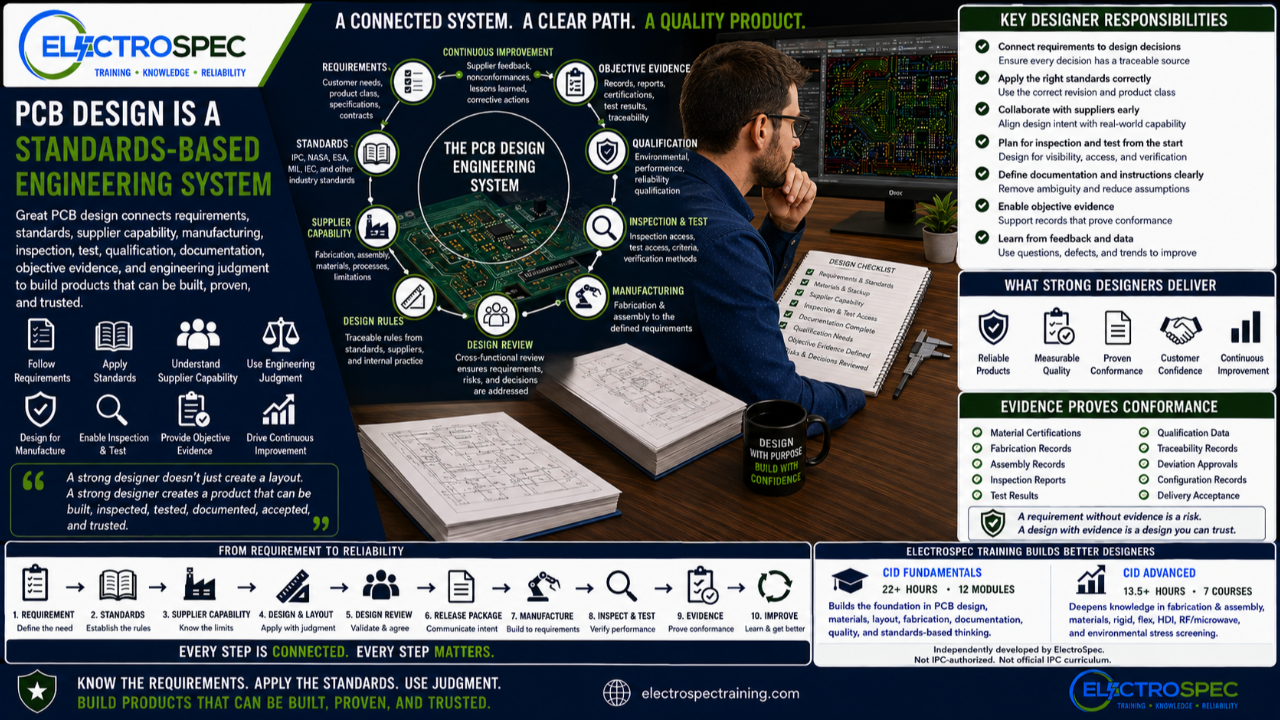
PCB design is often described as layout.
That is too narrow.
A PCB designer does more than place parts and route traces.
A strong PCB designer translates requirements into a product that can be fabricated, assembled, inspected, tested, documented, accepted, and trusted.
That requires more than CAD skill.
It requires standards knowledge, requirement flow-down, supplier awareness, manufacturing understanding, inspection planning, test strategy, documentation discipline, objective evidence, and engineering judgment.
PCB design is not just an activity.
PCB design is a standards-based engineering system.
Design Starts with Requirements, Not Routing
A PCB does not begin with a trace.
It begins with a requirement.
That requirement may come from a customer need, product specification, contract, drawing, standard, product class, environmental condition, qualification plan, or customer flow-down.
Before layout begins, the designer should understand:
- What must the product do?
- What environment will it experience?
- What product class applies?
- What standards are invoked?
- What customer requirements control the design?
- What materials are required or restricted?
- What fabrication and assembly processes will be used?
- How will the product be inspected and tested?
- What evidence will prove conformance?
When those questions are ignored, the layout may look complete, but the design may not support the real obligation.
Standards Provide the Framework
Standards give designers structure.
They help define materials, spacing, conductors, board construction, fabrication expectations, soldering requirements, inspection criteria, documentation needs, product class expectations, and reliability considerations.
But standards do not eliminate judgment.
They do not create the product by themselves.
The designer must understand which standards apply, which revision applies, what product class applies, how customer requirements modify the baseline, and how the requirement must be implemented in the design.
A standard can define the rule.
The designer must apply it correctly.
Traceability Connects the System
Standards traceability is the thread that connects the entire design system.
A design decision should be traceable to its source.
That source may be:
- customer drawing
- contract requirement
- IPC standard
- product class
- NASA requirement
- ESA requirement
- military specification
- IEC requirement
- material requirement
- fabrication limit
- assembly process
- inspection criterion
- test requirement
- qualification plan
- supplier capability
- engineering judgment
Without traceability, decisions can become opinions.
With traceability, decisions become part of the engineering record.
Supplier Capability Matters
A design must be buildable.
Supplier capability helps the designer understand what can be fabricated and assembled reliably.
Fabricators and assemblers can provide critical input on stackup, materials, copper thickness, drill sizes, via structures, solder mask, surface finish, controlled impedance, panelization, soldering process, cleaning, coating, inspection, and test access.
Supplier input should be used early.
But supplier capability does not automatically override customer requirements or invoked standards.
The designer must balance what is required with what can be built reliably.
That balance requires judgment.
Design Rules Must Be Understood
Design rules are useful, but not all design rules have the same authority.
Some come from standards.
Some come from customers.
Some come from supplier capability.
Some come from internal company practice.
Some come from ECAD tool defaults.
Some come from engineering judgment.
A strong designer knows the source of the rule.
A rule without traceability is just a number.
A rule with traceability becomes part of the design basis.
DRC Is Useful, But It Is Not Proof
Design rule checks matter.
A clean DRC report can catch many layout errors.
But DRC only proves that the layout passed the rules entered into the tool.
It does not prove the rules were correct.
It does not prove manufacturability.
It does not prove inspection access.
It does not prove testability.
It does not prove reliability.
It does not prove qualification readiness.
It does not prove customer conformance.
DRC is a checkpoint.
It is not the finish line.
Design Review Creates Accountability
A strong design review brings the system together.
It should confirm requirements, standards, supplier capability, materials, stackup, assembly process, inspection access, testability, qualification risk, documentation, and objective evidence.
The design review should ask:
Can this product be built, inspected, tested, accepted, documented, and trusted?
That question changes the review from a meeting into an accountability point.
It is where standards become action.
It is where assumptions become decisions.
It is where risks become documented.
The Release Package Communicates Intent
The release package is where design intent becomes manufacturing instruction.
Fabrication drawings, assembly drawings, BOMs, standards notes, material requirements, inspection requirements, test requirements, coating requirements, cleaning requirements, qualification requirements, and objective evidence requirements must tell one clear story.
A strong release package reduces assumptions.
A weak release package creates risk.
If the requirement is not documented clearly, the supplier may have to guess.
Guessing is not engineering.
Supplier Questions Are Feedback
Supplier questions should not be treated only as interruptions.
They are design feedback.
They reveal unclear requirements, missing documentation, manufacturability concerns, inspection limitations, test access issues, material concerns, and possible gaps in traceability.
A good designer listens to supplier questions.
A strong organization captures those questions and uses them to improve future design rules, drawing templates, release checklists, supplier reviews, and training.
Every supplier question is a chance to improve the system.
Nonconformances Are Also Feedback
Nonconformances, defects, escapes, rework, supplier findings, and corrective actions should be traced back into the design process.
Not every defect is caused by design.
But many defects reveal design-related contributors, such as unclear documentation, poor inspection access, weak test access, difficult manufacturability, inadequate material selection, supplier capability mismatch, or missing requirement flow-down.
A corrective action should do more than fix one part.
It should improve the system.
The best organizations do not only correct problems.
They learn from them.
Objective Evidence Proves Conformance
Objective evidence is often collected by quality, manufacturing, test, or suppliers.
But designers influence whether evidence can be created.
Design decisions affect what can be inspected, what can be tested, what can be documented, what can be qualified, and what can be proven.
Objective evidence may include:
- material certifications
- fabrication records
- assembly records
- inspection reports
- test results
- qualification data
- traceability records
- deviation approvals
- configuration records
A requirement without evidence is vulnerable.
A design that supports evidence is easier to trust.
PCB Design Is a Lifecycle Discipline
PCB design affects the entire product lifecycle.
A layout decision may affect fabrication.
A material decision may affect soldering and reliability.
A component placement decision may affect inspection.
A test point decision may affect verification.
A coating note may affect masking, inspection, and rework.
A stackup decision may affect impedance, cost, supplier capability, and qualification.
A documentation decision may affect product acceptance.
The designer is not only creating geometry.
The designer is shaping the product’s ability to move through manufacturing and survive real use.
CID Builds the Foundation
ElectroSpec’s CID Fundamentals course helps designers build the standards-based foundation needed for PCB design.
The course includes 22+ hours of on-demand training across 12 structured modules covering materials, layout principles, mechanical and electrical considerations, thermal management, component technologies, interconnections, fabrication requirements, documentation, quality assurance, manufacturability, and standards-based design thinking.
That foundation matters because strong PCB design requires more than knowing where to route a trace.
It requires understanding how design decisions affect the full product system.
CID Advanced Builds the Larger Framework
ElectroSpec CID Advanced expands into advanced design areas, including:
- PCB Fabrication & Assembly
- PCB Materials
- Rigid PCB Design
- Flexible PCB Design
- HDI PCB Design
- RF/Microwave PCB Design
- Environmental Stress Screening
These topics help designers connect advanced requirements to real products.
Flex design requires understanding materials, bend areas, stiffeners, and mechanical use.
HDI design requires understanding microvias, lamination, supplier capability, and reliability.
RF and microwave design require understanding stackup, dielectric properties, impedance, copper, and fabrication control.
Environmental stress requires understanding shock, vibration, thermal cycling, humidity, qualification, and evidence.
CID Advanced helps designers move from isolated technical topics into a connected design system.
Standards Do Not Replace Judgment
Even with strong standards, the designer still needs judgment.
The designer must balance:
- performance
- manufacturability
- reliability
- inspection access
- testability
- cost
- schedule
- supplier capability
- customer requirements
- qualification risk
- documentation burden
- objective evidence needs
There is rarely one perfect answer.
There is usually a best answer for the requirement, the product, the process, and the risk.
That is engineering judgment.
Independently Developed by ElectroSpec
ElectroSpec’s CID and CID Advanced courses are independently developed by ElectroSpec.
They are not IPC-authorized training and they are not official IPC curriculum.
ElectroSpec developed these courses to provide practical, standards-connected, manufacturing-aware design training for students preparing for CID and CID+ certification.
The goal is not simply to teach PCB layout.
The goal is to help designers understand the complete standards-based engineering system behind reliable electronics.
Final Thought
PCB design is not just layout.
It is not just CAD.
It is not just DRC.
It is not just documentation.
It is a connected engineering system.
Requirements define the need.
Standards provide the framework.
Supplier capability shapes what can be built.
Design rules guide implementation.
Design review creates accountability.
The release package communicates intent.
Supplier questions provide feedback.
Nonconformances create lessons.
Objective evidence proves conformance.
Engineering judgment ties it all together.
A strong PCB designer does not only create a board.
A strong PCB designer creates a product that can be built, inspected, tested, documented, accepted, and trusted.
That is the mindset ElectroSpec builds through CID and CID Advanced training.
Related ElectroSpec Training
ElectroSpec’s CID Fundamentals course provides 22+ hours of on-demand PCB design training across 12 structured modules.
ElectroSpec’s CID Advanced training expands into PCB Fabrication & Assembly, PCB Materials, Rigid PCB Design, Flexible PCB Design, HDI PCB Design, RF/Microwave PCB Design, and Environmental Stress Screening.
Together, these courses help designers build the standards-connected foundation needed for CID and CID+ certification preparation.
Series Wrap-Up
This standards traceability series covered:
- Standards Traceability: The Missing Skill in PCB Design Training
- From Requirement Flow-Down to PCB Layout
- Design Rules, Supplier Capability, and Engineering Judgment
- Why Design Rule Checks Do Not Prove a Good Design
- The Design Review Is Where Standards Become Accountability
- The Release Package: Where Design Intent Becomes Manufacturing Instruction
- Supplier Questions Are Design Feedback
- Design Lessons from Nonconformances and Corrective Actions
- The Designer’s Role in Objective Evidence
- PCB Design Is a Standards-Based Engineering System
The message is simple:
Know the requirements. Apply the standards. Use judgment. Build products that can be proven and trusted.
IPC CID Certification — ElectroSpec
IPC CID+ Certification — ElectroSpec
IPC CID/CID+ Bundle — Complete PCB Design Certification — ElectroSpec