Designing for Inspection: If You Cannot Inspect It, Can You Accept It?
Jul 30, 2026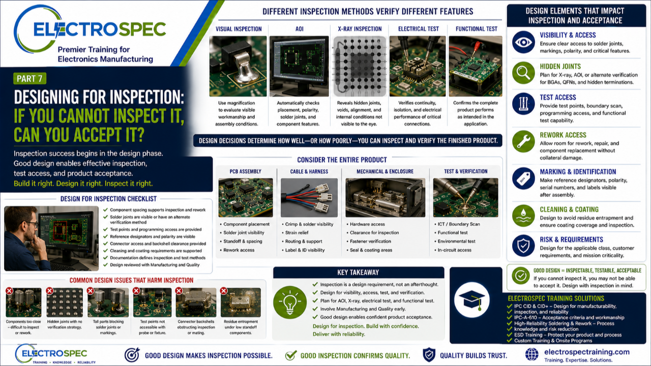
In the previous article, we discussed why J-STD-001 is an important process standard, but why training must match the role, process, and manufacturing responsibility.
Now we need to move to another design responsibility that is often overlooked.
Inspection.
Many people think inspection begins after the product is built.
That is only partly true.
Inspection is performed after or during manufacturing, but inspection success is heavily influenced by design.
If the designer creates a product that is difficult to inspect, obstructed, hidden, inaccessible, or poorly documented, the inspector may be placed in an impossible position.
That leads to a practical question:
If you cannot inspect it, can you confidently accept it?
Inspection Should Be Considered During Design
Designers are not usually responsible for final inspection.
However, designers influence what can be inspected, how it can be inspected, and whether the inspection method is realistic.
Design decisions affect:
- visual access
- component spacing
- solder joint visibility
- polarity marking visibility
- connector access
- test point placement
- rework access
- AOI coverage
- X-ray requirements
- cleaning verification
- conformal coating inspection
- hardware verification
- cable and wire routing inspection
- final acceptance confidence
If inspection is not considered until production, the organization may discover too late that some critical features are difficult or impossible to verify.
IPC-A-610 Requires an Inspectable Product
IPC-A-610 is commonly used to evaluate the acceptability of completed electronic assemblies.
Inspectors use it to determine whether workmanship conditions are acceptable, process indicators, or defects.
But IPC-A-610 does not magically make hidden features visible.
If the product design blocks access to a solder joint, hides a termination, obstructs a marking, or prevents normal inspection, the company still needs a valid verification method.
That may require:
- X-ray inspection
- AOI
- functional test
- electrical test
- process validation
- first article inspection
- destructive evaluation where appropriate
- special tooling
- documented alternate inspection methods
The designer should understand these needs before the product is released.
Hidden Solder Joints Need a Verification Strategy
Modern electronics often use components with hidden or partially hidden solder joints.
Examples include:
- BGAs
- bottom termination components
- QFNs
- LGAs
- shielded components
- dense connectors
- stacked assemblies
- components under mechanical hardware
- assemblies with limited viewing angles
These packages may be necessary for electrical, thermal, size, or performance reasons.
But when they are selected, the design team must also define how the joints will be verified.
A hidden solder joint may not be visually inspectable.
That does not mean it cannot be accepted.
It means the organization needs a defined inspection or verification strategy.
AOI Has Limits
Automated optical inspection can be powerful.
It can help verify component presence, polarity, placement, markings, solder joint features, and other visible conditions.
But AOI depends on visibility, lighting, angles, programming, contrast, component geometry, and access.
AOI may struggle with:
- hidden solder joints
- obstructed terminations
- reflective surfaces
- shadowing
- tall adjacent components
- inconsistent markings
- unusual component packages
- dense layouts
- post-coating inspection
- cable or hardware obstruction
Designers should not assume AOI can inspect everything.
Design should support AOI where AOI will be used.
X-Ray Can Help, But It Is Not a Universal Fix
X-ray inspection can support evaluation of hidden solder joints and internal features, especially where visual inspection is limited.
It may be useful for:
- BGAs
- bottom termination components
- voiding evaluation
- hidden joints
- through-hole fill assessment in some cases
- internal alignment
- certain connector or package conditions
However, X-ray is not always simple.
It may require trained personnel, proper equipment, defined acceptance criteria, image interpretation skill, customer agreement, and documented inspection methods.
X-ray can also add time and cost.
A design that relies on X-ray should intentionally include that requirement in the inspection and quality planning process.
Test Access Matters
Inspection is not only visual.
Electrical test is often essential for verifying product function and continuity.
Designers should consider:
- test point location
- test point size
- fixture access
- probe access
- boundary scan needs
- functional test needs
- in-circuit test needs
- programming access
- connector access
- high-voltage spacing where applicable
- safe test setup
If test access is not designed in, verification may become expensive, slow, incomplete, or unreliable.
A product that cannot be tested efficiently may create problems throughout production and field support.
Rework Access Matters Too
Inspection and rework are closely connected.
If inspection finds a defect, the organization may need to repair or rework the product.
Designers should consider whether components can be safely removed, replaced, touched up, cleaned, and reinspected.
Poor rework access can create risks such as:
- lifted pads
- thermal damage
- damaged adjacent components
- insulation damage
- contamination
- excessive handling
- repeat defects
- scrap
- delayed delivery
A design that cannot be reworked may still be acceptable in some cases, but that should be a deliberate decision based on product risk, cost, and reliability—not an accidental result of dense layout.
Markings Must Be Visible
Polarity, orientation, reference designators, labels, serialization, and identification markings matter.
If markings are hidden after assembly, inspection becomes harder.
Designers should consider:
- component polarity visibility
- pin 1 indicators
- reference designators
- board revision markings
- serialization
- barcodes
- cable labels
- connector identification
- test labels
- safety markings
- customer-required markings
If the inspector cannot verify orientation, identity, or configuration, the organization may need another verification method.
Clear marking supports inspection, test, maintenance, and field service.
Cleaning and Coating Must Be Inspectable
Cleaning and conformal coating also create inspection challenges.
A design may trap residues under components, around connectors, near low standoff parts, or between dense features.
Conformal coating may be difficult to apply or inspect if spacing, masking, component geometry, or coverage areas are not considered.
Designers should think about:
- component standoff
- residue entrapment
- cleaning compatibility
- no-clean flux expectations
- coating keep-out areas
- coating thickness inspection
- masking requirements
- connector protection
- test point access after coating
- rework after coating
Inspection of cleanliness and coating is not only a quality issue.
It is a design issue.
Cable and Harness Inspection Also Needs Access
Designing for inspection is not limited to printed circuit assemblies.
Cable and wire harness assemblies also require inspection access.
For harness design, consider:
- connector backshell access
- crimp inspection
- solder cup visibility
- shield termination visibility
- lacing and tying inspection
- bend radius
- strain relief
- marking and identification
- wire routing
- service loops
- splice access
- documentation
- continuity test access
- pull test or process validation where applicable
A harness may meet electrical continuity but still have workmanship or reliability concerns if routing, support, strain relief, or terminations cannot be properly verified.
The Inspector Should Be Involved Before Release
Design reviews should include inspection input before the product is released.
Inspectors and quality engineers can help identify:
- inaccessible solder joints
- difficult viewing angles
- unclear acceptance criteria
- missing test points
- poor marking visibility
- rework limitations
- hidden defects
- documentation gaps
- customer flow-down concerns
- inspection method limitations
This feedback is far more valuable before production than after the first build fails inspection.
Design for Inspection Is Part of Design for Reliability
Inspection is not the goal.
Reliable product performance is the goal.
Inspection is one method of verifying that the product was built correctly.
When designers make inspection difficult, the organization loses confidence in product acceptance.
When designers make inspection practical, the organization improves:
- defect detection
- inspection consistency
- production yield
- rework planning
- customer confidence
- audit readiness
- field reliability
Design for inspection supports design for reliability.
A Better Design Review Question
Instead of asking only:
“Can we build it?”
design teams should also ask:
“Can we verify that it was built correctly?”
That question changes the design review.
It forces the team to think about visibility, test access, acceptance criteria, inspection methods, records, and product confidence.
Final Thought
Inspection should not be an afterthought.
Designers do not need to become inspectors, but they do need to understand how their design decisions affect inspection and verification.
If a product cannot be visually inspected, tested, measured, or otherwise verified, the organization must define another valid method of acceptance.
A good design is not only manufacturable.
It is inspectable.
It gives operators a realistic process, inspectors a clear verification path, and customers confidence that the product meets the requirement.
Related ElectroSpec Training
ElectroSpec’s IPC CID and CID+ training programs help PCB designers and product engineers understand how design decisions affect manufacturability, inspection access, testability, product acceptance, and reliability.
ElectroSpec also offers IPC-A-610 certification for personnel who need to understand completed electronic assembly acceptance criteria and how inspection supports product conformance.
Coming Next
Designing for Qualification: Shock, Vibration, Thermal, Humidity, and Real-World Use
In the next article, we will explain why environmental qualification is not something added at the end. It must be designed into the product through material selection, layout, mechanical support, thermal management, interconnect design, solder joint reliability, coating, and process control.