Design Rules, Supplier Capability, and Engineering Judgment
Aug 26, 2026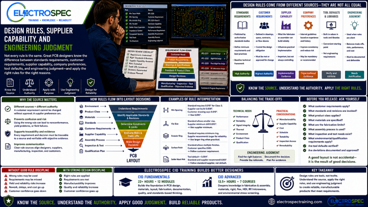
PCB designers work with rules every day.
Clearance rules.
Trace width rules.
Via rules.
Annular ring rules.
Solder mask rules.
Impedance rules.
Component placement rules.
Fabrication rules.
Assembly rules.
Inspection rules.
But not every rule has the same authority.
Some rules come from standards.
Some come from customer requirements.
Some come from supplier capability.
Some come from company design practices.
Some come from tool defaults.
Some come from engineering judgment.
A strong designer knows the difference.
That difference matters because treating every rule the same can create problems. A supplier preference may be flexible. A customer requirement may not be. A tool default may be convenient, but it may not be correct for the product. A company guideline may work for many designs, but not every design.
Good PCB design requires knowing which rules must be followed, which rules can be adjusted, and which rules require engineering review.
Not Every Design Rule Is a Requirement
A design rule is often entered into an ECAD tool as a number.
Minimum trace width.
Minimum spacing.
Minimum drill size.
Minimum solder mask web.
Minimum annular ring.
But the number alone does not tell the designer where it came from.
A rule may be based on:
- a published standard
- a customer drawing
- a contract requirement
- a supplier capability limit
- a preferred manufacturing guideline
- an internal company rule
- an electrical performance need
- a voltage requirement
- a reliability concern
- a historical practice
- a tool library default
- engineering judgment
Those sources are not equal.
A standard requirement and a tool default should not carry the same weight.
A customer flow-down and a supplier preference should not be treated the same way.
The designer must understand the source before making the decision.
Supplier Capability Is Not the Same as a Standard
Supplier capability matters.
Designers should know what the fabricator and assembler can build reliably.
Supplier input can help avoid yield problems, schedule delays, unnecessary cost, and manufacturability issues.
But supplier capability is not automatically the same as a standards requirement.
A supplier may say, “We prefer this spacing.”
That may mean it improves yield.
It may mean it reduces cost.
It may mean it fits their process better.
It may mean they can build tighter geometry, but do not recommend it unless necessary.
That is useful information.
But the designer still needs to know whether the product requirement allows the change.
For example, a supplier preference cannot override a customer requirement unless the customer approves the deviation.
A supplier capability table cannot replace the design standard if the standard or contract requires something different.
Supplier capability should inform the design.
It should not silently rewrite the requirement.
Customer Requirements Usually Control the Design Obligation
Customer requirements often carry the strongest authority.
They may appear in:
- drawings
- specifications
- purchase orders
- contracts
- qualification plans
- acceptance criteria
- material requirements
- inspection requirements
- documentation requirements
When customer requirements are flowed down, designers must understand them before layout decisions are finalized.
If the customer requires a specific class, material, finish, test, inspection method, traceability record, or qualification result, that requirement must be addressed.
If a supplier suggests a different approach, the design team may need customer approval before making the change.
That is why requirement flow-down matters.
The designer must know what controls the design.
Standards Provide the Technical Framework
Standards help designers understand the technical framework.
They may define requirements, design considerations, material expectations, process expectations, acceptability criteria, and reliability considerations.
For PCB design, standards may help address:
- spacing
- conductors
- board construction
- materials
- rigid board design
- flexible board design
- RF and microwave design
- bare board acceptability
- soldered assembly requirements
- finished assembly acceptability
- coating
- solderability
- documentation
- quality and reliability
Standards help create consistency.
They help reduce ambiguity.
They help designers communicate with fabricators, assemblers, inspectors, customers, and quality teams.
But standards still require interpretation.
The designer must understand which standard applies, what product class applies, what revision applies, and whether customer requirements add or modify the baseline.
Company Design Rules Can Be Useful
Many companies have internal PCB design rules.
These may reflect lessons learned, supplier preferences, common product needs, manufacturing experience, design reuse, field history, or conservative engineering practice.
Internal rules can be very helpful.
They can improve consistency across designs.
They can reduce recurring mistakes.
They can help newer designers avoid known problems.
But internal rules should still be understood.
A designer should know whether an internal rule is:
- mandatory
- recommended
- preferred
- based on supplier capability
- based on a past failure
- based on a customer requirement
- based on a specific product family
- based on manufacturing yield
- based on engineering judgment
Internal rules are strongest when they are traceable.
A rule with a known reason is easier to apply correctly.
Tool Defaults Are Not Engineering Requirements
ECAD tools are powerful.
Constraint managers, design rule checks, libraries, templates, and automation can help designers control complex layouts.
But tool defaults are not engineering requirements.
A tool may contain a default clearance, default trace width, default via, default solder mask expansion, or default component rule.
That does not mean the default is correct for the product.
The designer must verify that tool settings match:
- customer requirements
- applicable standards
- product class
- voltage and current needs
- material system
- fabrication capability
- assembly process
- inspection needs
- test needs
- reliability requirements
A design rule check only checks the rules that were entered.
If the rules are wrong, the tool may approve a bad design.
Tools support engineering judgment.
They do not replace it.
Engineering Judgment Fills the Gaps
Not every decision is answered directly by a rule.
Designers often face tradeoffs.
For example:
A denser layout may reduce size but make inspection harder.
A tighter via structure may improve routing but increase fabrication risk.
A material may improve performance but increase cost and lead time.
A component placement may improve signal integrity but reduce rework access.
A coating requirement may improve environmental protection but complicate test and repair.
A high-reliability requirement may require conservative design choices beyond minimum rules.
This is where engineering judgment matters.
The designer must understand the requirements, risks, standards, supplier capability, and product environment, then make a defensible decision.
Minimum Capability Is Not Always the Best Design Target
Just because a supplier can build something does not mean the design should push that limit.
Minimum feature size is not always the best design practice.
A fabricator may be capable of very fine lines, tight spacing, small vias, or complex constructions, but pushing process limits may increase cost, reduce yield, extend schedule, or increase reliability risk.
Designers should ask:
- Is this feature necessary?
- Is the supplier capability proven for this product class?
- Does the design need this density?
- Does the environment increase risk?
- Does the product require Class 3 performance?
- Will qualification testing stress this feature?
- Is there a more robust design option?
- What is the cost and yield impact?
- What evidence supports this choice?
Good design is not always the smallest possible feature.
Good design is the right feature for the product.
Design Rules Should Be Traceable
A strong design rule set should have traceability.
For each major rule, the team should be able to answer:
- What is the rule?
- Where did it come from?
- Is it mandatory or preferred?
- What risk does it control?
- What standard or requirement supports it?
- What supplier capability supports it?
- What product class does it apply to?
- What verification method confirms it?
- Who can approve a change?
This is especially important for high-reliability products.
When a customer, auditor, supplier, inspector, or failure analysis team asks why a design decision was made, the answer should not be, “That was the default.”
The answer should connect back to the requirement, standard, analysis, or documented judgment.
Supplier Input Should Be Used Early
Supplier input is most valuable before layout release.
Fabricators and assemblers can help identify:
- stackup concerns
- material availability
- copper thickness concerns
- drill and via limitations
- HDI risks
- flex construction risks
- solder mask concerns
- surface finish concerns
- panelization issues
- assembly access problems
- inspection challenges
- test limitations
- coating or cleaning concerns
Early supplier review can prevent redesign.
But supplier input should be reviewed against the full requirement set.
The supplier can help the designer understand what is practical.
The designer must still ensure the design meets the customer and standards obligations.
Designers Must Balance Authority and Practicality
PCB design often requires balancing what is required with what is practical.
The designer may need to balance:
- customer requirements
- standards requirements
- supplier capability
- company rules
- product performance
- material availability
- cost
- schedule
- reliability
- manufacturability
- inspection
- testability
This balance is not always simple.
A customer requirement may create manufacturing difficulty.
A supplier capability may limit design options.
A standard may define a requirement that affects layout density.
A reliability concern may justify a more conservative design.
The designer must understand the hierarchy and then work through the tradeoffs.
A Practical Rule Hierarchy
A useful way to think about design rules is by authority.
At the top are controlling requirements such as contracts, customer drawings, and customer specifications.
Next are invoked standards, product class, and formal specifications.
Then come program requirements, material requirements, qualification requirements, and process requirements.
Then supplier capability and company design practices help shape practical implementation.
Finally, engineering judgment ties the system together.
This does not mean supplier input is unimportant.
It means supplier input must be used within the controlling requirement framework.
CID Builds the Foundation for Rule Interpretation
ElectroSpec’s CID Fundamentals course helps designers build the foundation needed to understand PCB design rules and requirements.
The course includes 22+ hours of on-demand training across 12 structured modules covering materials, layout principles, mechanical and electrical considerations, thermal management, component technologies, interconnections, fabrication requirements, documentation, quality assurance, manufacturability, and standards-based design thinking.
That foundation helps designers understand why rules exist, where they come from, and how they affect real products.
CID is not only about learning numbers.
It is about learning how to think like a standards-based designer.
CID Advanced Builds the Supplier and Technology Context
ElectroSpec CID Advanced builds on that foundation with advanced courses in:
- PCB Fabrication & Assembly
- PCB Materials
- Rigid PCB Design
- Flexible PCB Design
- HDI PCB Design
- RF/Microwave PCB Design
- Environmental Stress Screening
These areas help designers understand how rules change across board technologies and environments.
A flex design rule may be driven by material and bend reliability.
An RF rule may be driven by impedance, stackup, dielectric properties, and fabrication tolerance.
An HDI rule may be driven by microvia capability and reliability.
An environmental rule may be driven by shock, vibration, thermal cycling, humidity, and qualification.
Advanced design requires understanding the reason behind the rule.
Design Rules Should Be Reviewed Before Release
Before releasing a PCB layout, designers should review the rule set.
Key questions include:
- Are the correct customer requirements included?
- Are the correct standards and revisions included?
- Is the correct product class applied?
- Are material requirements included?
- Are fabrication rules based on supplier capability?
- Are assembly requirements included?
- Are inspection and test needs considered?
- Are environmental and qualification needs included?
- Are internal company rules appropriate for this product?
- Are tool defaults reviewed and adjusted?
- Are deviations documented and approved?
This review helps prevent late surprises.
It also helps ensure that design rule checks are meaningful.
Independently Developed by ElectroSpec
ElectroSpec’s CID and CID Advanced courses are independently developed by ElectroSpec.
They are not IPC-authorized training and they are not official IPC curriculum.
ElectroSpec developed these courses to provide practical, standards-connected, manufacturing-aware design training for students preparing for CID and CID+ certification.
The focus is not only on knowing design rules.
The focus is on understanding how rules, requirements, supplier capability, and engineering judgment work together.
Final Thought
Design rules are important.
Supplier capability is important.
Company practices are important.
Tool constraints are important.
But none of them should be used blindly.
A strong PCB designer knows where each rule comes from, what authority it has, what risk it controls, and how it affects the product.
The goal is not merely to pass a design rule check.
The goal is to design a product that meets requirements, can be manufactured, can be inspected, can be tested, can be documented, and can be trusted.
Design rules guide the layout.
Engineering judgment builds the product.
Related ElectroSpec Training
ElectroSpec’s CID Fundamentals course provides 22+ hours of on-demand PCB design training across 12 structured modules.
ElectroSpec’s CID Advanced training expands into PCB Fabrication & Assembly, PCB Materials, Rigid PCB Design, Flexible PCB Design, HDI PCB Design, RF/Microwave PCB Design, and Environmental Stress Screening.
Together, these courses help designers build the standards-connected foundation needed for CID and CID+ certification preparation.
Coming Next
Why Design Rule Checks Do Not Prove a Good Design
In the next article, we will discuss why passing an ECAD design rule check is useful, but does not prove manufacturability, reliability, inspection access, testability, qualification readiness, or customer conformance.
IPC CID Certification — ElectroSpec
IPC CID+ Certification — ElectroSpec
IPC CID/CID+ Bundle — Complete PCB Design Certification — ElectroSpec