NASA, Military, ESA, IEC, and IPC: Where Each Standard System Fits
Aug 20, 2026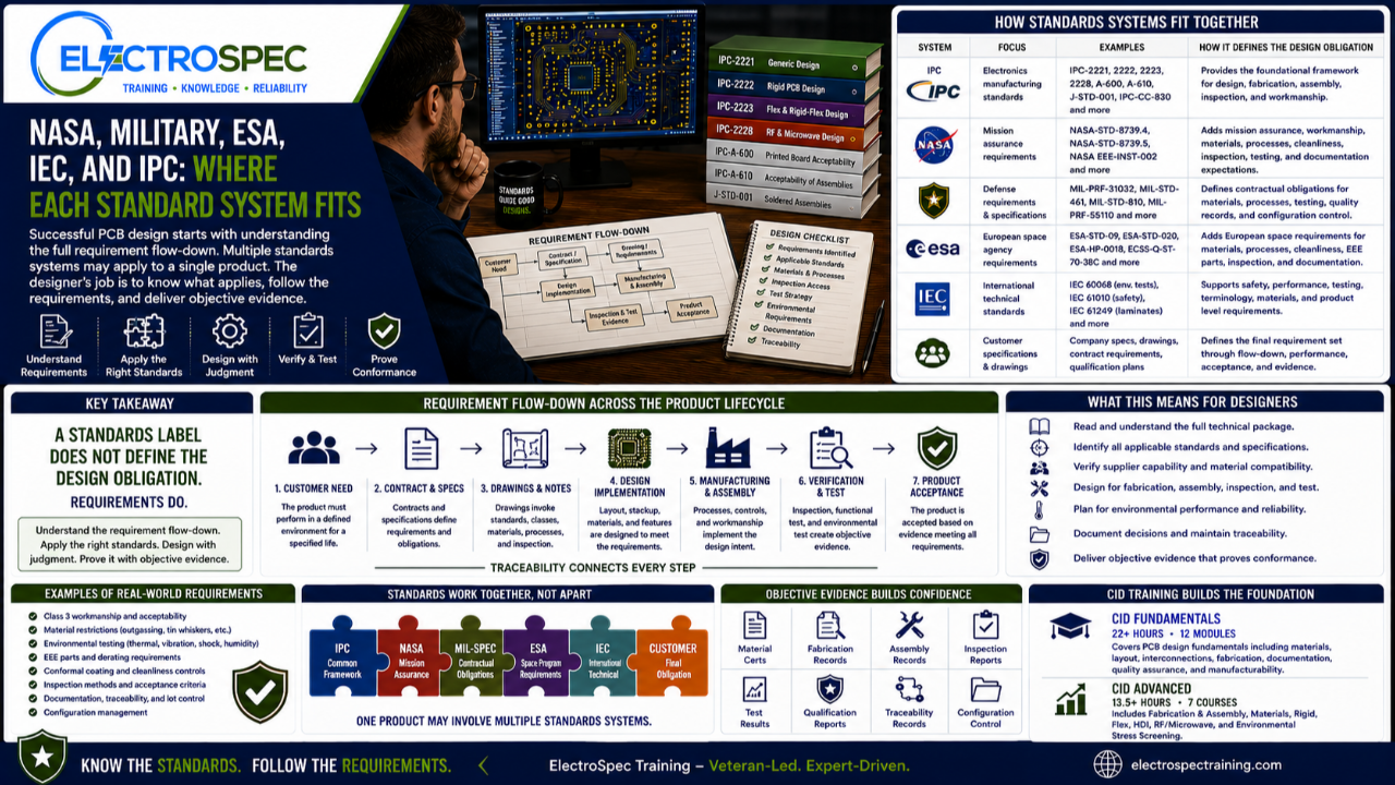
Electronics design and manufacturing do not operate under one universal standard.
IPC is important.
But IPC is not the only standards system designers may encounter.
Depending on the product, customer, contract, industry, mission, and environment, designers may also need to understand NASA requirements, military specifications, European Space Agency requirements, IEC standards, company specifications, customer drawings, qualification plans, material restrictions, and program-specific flow-downs.
That is why designers need standards literacy.
They do not need to memorize every document in every standards system.
But they do need to understand where different requirement systems fit, how requirements flow down, and how to trace design decisions back to the correct source.
That is a major part of professional PCB design judgment.
IPC Provides a Common Electronics Manufacturing Framework
IPC standards are widely used across electronics design and manufacturing.
They help provide a common framework for printed board design, fabrication, assembly, soldering, inspection, acceptability, materials, documentation, and workmanship expectations.
For PCB designers, IPC design standards help establish foundational and technology-specific guidance.
For manufacturing and inspection teams, IPC-related standards help connect assembly requirements, bare board acceptability, finished assembly acceptability, soldering requirements, and product class expectations.
IPC gives many organizations a shared language.
That matters because electronics manufacturing involves many groups:
- designers
- fabricators
- assemblers
- process engineers
- inspectors
- quality engineers
- customers
- auditors
- suppliers
- program managers
Without a shared standards language, communication becomes subjective.
IPC helps reduce that ambiguity.
IPC Is a Foundation, Not the Entire Requirement Set
IPC standards can be an excellent foundation.
But a foundation is not always the complete requirement set.
A product may invoke IPC requirements and still require additional customer, contract, agency, military, medical, aerospace, space, or environmental requirements.
For example, a drawing may reference IPC Class 3 expectations.
But the contract may also impose material restrictions, process documentation, test requirements, traceability records, configuration control, or qualification evidence.
A customer specification may add stricter requirements.
A program may require NASA, ESA, military, or IEC-related requirements.
That means designers cannot stop at asking, “What IPC standard applies?”
They must ask, “What full requirement set applies to this product?”
NASA Requirements Often Emphasize Mission Assurance
NASA-related requirements are often associated with mission assurance, workmanship, reliability, process discipline, material control, inspection, testing, and documentation.
For space and mission-critical products, the concern is not only whether the product can be built.
The concern is whether the product can survive the intended mission environment and perform when needed.
NASA-related requirements may influence areas such as:
- workmanship expectations
- material selection
- process control
- soldering and assembly practices
- cable and harness workmanship
- conformal coating
- staking and bonding
- cleanliness
- inspection
- outgassing concerns
- documentation
- test evidence
- risk control
- mission assurance
Not every aerospace product is a NASA product.
Not every space-related product uses the same NASA requirements.
But designers working in these environments must understand that NASA-type requirements can add obligations beyond general commercial electronics practices.
Military Specifications Often Define Contractual Obligations
Military specifications and defense requirements often enter through contracts, drawings, program specifications, purchase orders, qualification requirements, and customer flow-downs.
These requirements may affect:
- materials
- fabrication
- inspection
- qualification
- product acceptance
- supplier approval
- documentation
- traceability
- testing
- configuration control
- process control
- environmental performance
- quality records
Military specifications are not simply technical suggestions when they are contractually invoked.
They become obligations.
That is why designers must understand requirement flow-down.
A design team may believe they are only designing a PCB, but the contract may require specific materials, testing, qualification, workmanship, inspection, or documentation.
If those requirements are missed early, the problem may not appear until supplier review, customer inspection, audit, qualification testing, or delivery.
ESA Requirements Support European Space Applications
The European Space Agency has its own requirement ecosystem for space applications.
ESA-related requirements may influence materials, manufacturing controls, cleanliness, soldering, assembly, inspection, qualification, documentation, and reliability expectations.
For designers working on European space programs or suppliers supporting ESA-related work, the key lesson is the same:
The design obligation comes from the invoked requirement set.
A product may use IPC as part of the baseline, but ESA requirements may add or modify expectations based on mission, customer, or contract needs.
Designers must understand what is actually flowed down.
They should not assume that IPC alone, NASA alone, ESA alone, or a general “space” label fully defines the requirement.
The actual requirement package must be reviewed.
IEC Standards Provide International Technical Frameworks
IEC standards are used internationally across many areas of electrical and electronic technology.
Depending on the product, IEC requirements may affect safety, environmental testing, reliability, component behavior, product performance, measurement methods, terminology, or system-level expectations.
For PCB designers, IEC may not always be the first design standard they use.
But IEC requirements may still appear through product safety requirements, environmental testing, customer specifications, system requirements, regulatory expectations, or international market needs.
That means designers must understand that PCB design decisions may be affected by standards outside the IPC ecosystem.
The PCB may be one part of a larger product compliance picture.
Customer Specifications Often Control the Final Obligation
In many cases, the customer specification is the controlling document.
The customer may invoke IPC standards, NASA requirements, ESA requirements, military specifications, IEC standards, company specifications, or unique product requirements.
The customer may also define:
- product class
- environmental conditions
- inspection requirements
- testing requirements
- material restrictions
- documentation requirements
- traceability expectations
- qualification requirements
- acceptance criteria
- deviation approval process
- configuration control
This is why designers must read the requirement package carefully.
A customer specification may use IPC as a foundation, but it may also add requirements, clarify requirements, or impose stricter expectations.
Designers should never assume that a standard title alone tells the whole story.
Requirement Flow-Down Is the Designer’s Map
Requirement flow-down is the process of translating high-level customer, contract, system, and environmental requirements into design, fabrication, assembly, inspection, test, and documentation requirements.
A simple example might look like this:
Customer need leads to contract requirements.
Contract requirements lead to drawing notes and specifications.
Drawing notes invoke standards and product class.
Standards and product class affect materials, layout, fabrication, assembly, inspection, and test.
Inspection and test create objective evidence.
Objective evidence supports product acceptance.
That is the map.
When requirement flow-down is weak, teams may miss critical obligations.
When requirement flow-down is strong, design decisions are traceable, defensible, and easier to verify.
Standards Can Overlap
Different standards systems may address similar topics.
For example, multiple systems may address workmanship, soldering, materials, environmental stress, inspection, documentation, or reliability.
That does not mean the designer can choose whichever one is easiest.
The applicable requirement depends on what is invoked by the drawing, contract, customer specification, qualification plan, or governing program.
Designers must understand priority.
They should ask:
- What document controls?
- What standard is invoked?
- What revision applies?
- What class applies?
- Are there customer-specific additions?
- Are there conflicts between requirements?
- Who has authority to resolve conflicts?
- What objective evidence is required?
This is where design judgment and quality discipline meet.
Conflicts Must Be Resolved Before Production
Conflicting requirements should not be discovered during final inspection, qualification testing, or customer delivery.
They should be resolved early.
Examples of possible conflicts include:
- a customer drawing requiring one material while supplier capability suggests another
- a fabrication note that conflicts with a customer specification
- a coating requirement that conflicts with connector access
- an inspection requirement that is impossible due to hidden geometry
- a test requirement that lacks test access
- a reliability expectation that conflicts with the selected stackup or component package
- a qualification environment that was not considered in layout or mechanical support
When requirements conflict, designers should not guess.
They should elevate the issue, document the resolution, and ensure the drawing or technical package reflects the correct requirement.
Standards Traceability Supports Objective Evidence
High-reliability products often require objective evidence.
That evidence may include:
- drawings
- material certifications
- fabrication records
- assembly records
- inspection reports
- test results
- qualification records
- process control records
- training records
- configuration records
- nonconformance records
- deviation approvals
- corrective actions
Standards traceability helps connect those records to the requirement.
A design decision should not exist in isolation.
It should connect to a requirement source.
That requirement source should connect to verification.
Verification should produce evidence.
Evidence supports acceptance.
That is how engineering, manufacturing, and quality work together.
IPC, NASA, ESA, Military, and IEC Are Not Competitors in the Designer’s Mind
Designers should not think of these systems as mutually exclusive.
A product may involve more than one.
IPC may provide the PCB design and manufacturing foundation.
A military contract may define additional defense obligations.
A NASA or ESA program may define mission assurance expectations.
IEC may influence product-level safety or environmental requirements.
Customer specifications may tie them together.
The designer’s job is not to pick a favorite standards system.
The designer’s job is to understand which requirements apply to the product and how to implement them correctly.
CID Builds Standards Literacy
ElectroSpec’s CID Fundamentals course helps designers build the foundation needed to understand printed board design requirements.
The course includes 22+ hours of on-demand training across 12 structured modules covering materials, layout principles, mechanical and electrical considerations, thermal management, component technologies, interconnections, fabrication requirements, documentation, quality assurance, manufacturability, and standards-based design thinking.
That foundation is important because designers need to understand how requirements affect real products.
They need to know how design choices connect to fabrication, assembly, inspection, acceptance, reliability, and documentation.
CID Advanced Builds the Broader Design Framework
ElectroSpec CID Advanced builds on the foundation with advanced courses in:
- PCB Fabrication & Assembly
- PCB Materials
- Rigid PCB Design
- Flexible PCB Design
- HDI PCB Design
- RF/Microwave PCB Design
- Environmental Stress Screening
These areas help designers understand the larger requirement system.
Advanced designs often involve multiple standards, customer requirements, material considerations, environmental conditions, and reliability expectations.
CID Advanced helps designers connect those concerns into a practical design framework.
That matters for products used in aerospace, defense, space, medical, industrial, transportation, and other high-reliability environments.
Standards Do Not Replace Engineering Judgment
Even when the correct standards are identified, the designer still has to make decisions.
A standard may define requirements.
A customer may define expectations.
A qualification plan may define the environment.
But the designer still has to decide how to meet those requirements in the actual product.
That requires judgment.
The designer must balance:
- electrical performance
- manufacturability
- material availability
- fabrication capability
- inspection access
- test strategy
- thermal performance
- mechanical support
- cost
- schedule
- reliability
- customer requirements
Standards provide the rules.
Designers create the solution.
A Practical Standards Question for Every Design Review
Every design review should include a standards and requirements discussion.
Teams should ask:
- What requirements apply?
- What standards are invoked?
- What revision applies?
- What class applies?
- What customer flow-downs apply?
- What materials are required or restricted?
- What fabrication requirements apply?
- What assembly requirements apply?
- What inspection and test evidence is needed?
- What environmental conditions apply?
- What qualification requirements apply?
- What documentation is required?
- What conflicts need resolution?
These questions help prevent late surprises.
They also help designers make better decisions before the design is released.
Independently Developed by ElectroSpec
ElectroSpec’s CID and CID Advanced courses are independently developed by ElectroSpec.
They are not IPC-authorized training and they are not official IPC curriculum.
ElectroSpec developed these courses to provide practical, standards-connected, manufacturing-aware design training for students preparing for CID and CID+ certification.
The goal is not to memorize standards titles.
The goal is to understand how requirements flow into real design decisions.
Final Thought
IPC, NASA, military, ESA, IEC, and customer specifications all have roles in electronics design and manufacturing.
IPC often provides a strong foundation.
NASA and ESA may add mission assurance and space-related expectations.
Military specifications may define defense contract obligations.
IEC may support broader international technical and product requirements.
Customer specifications often determine the final requirement package.
The designer’s responsibility is to understand what applies.
A strong designer does not rely on a label.
A strong designer follows the requirement flow-down, traces decisions to standards, applies judgment, and supports the product with objective evidence.
That is how standards become reliable designs.
Related ElectroSpec Training
ElectroSpec’s CID Fundamentals course provides 22+ hours of on-demand PCB design training across 12 structured modules.
ElectroSpec’s CID Advanced training expands into PCB Fabrication & Assembly, PCB Materials, Rigid PCB Design, Flexible PCB Design, HDI PCB Design, RF/Microwave PCB Design, and Environmental Stress Screening.
Together, these courses help designers build the standards-connected foundation needed for CID and CID+ certification preparation.
Coming Next
Class 3 and High-Reliability Design: More Than Just a Label
In the next article, we will discuss why Class 3 is not merely a drawing note or marketing phrase, but a design and manufacturing responsibility that affects materials, fabrication, assembly, inspection, testing, documentation, and reliability.
IPC CID Certification — ElectroSpec
IPC CID+ Certification — ElectroSpec
IPC CID/CID+ Bundle — Complete PCB Design Certification — ElectroSpec