ECAD, MCAD, and Constraint Courses: Tools Need Standards Behind Them
Aug 11, 2026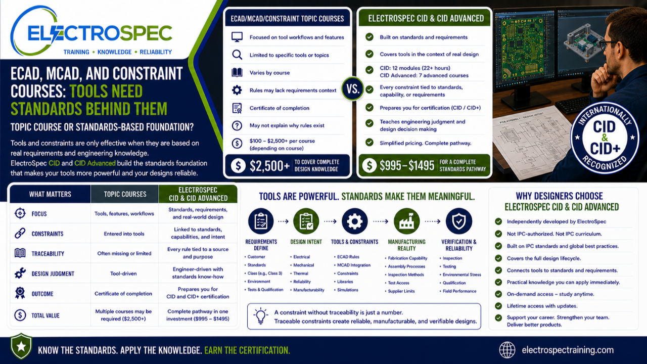
Modern PCB design depends heavily on tools.
Designers use ECAD tools, MCAD integration, constraint managers, design rule checks, library systems, simulation tools, collaboration platforms, and model-based workflows to manage increasingly complex products.
Those tools matter.
They help designers organize information, control design rules, reduce mistakes, communicate with mechanical teams, manage product data, and move designs toward fabrication and assembly.
But tools do not replace design knowledge.
A constraint is only useful if the designer understands the requirement behind it.
A model is only useful if it represents the right design intent.
A design rule is only useful if it is tied to the right standard, process capability, product class, or customer requirement.
That is why ECAD, MCAD, model-based design, and constraint training should be compared carefully.
The buyer should ask:
Is the course teaching tool workflow, or is it helping the designer understand the standards, requirements, and engineering decisions behind the tool?
That distinction matters.
Tools Help Manage Design Intent
ECAD and MCAD tools can be extremely valuable.
They help manage:
- board outline
- component placement
- mechanical fit
- keep-out areas
- connector alignment
- enclosure constraints
- mounting features
- stackup information
- design rules
- routing constraints
- clearance rules
- fabrication outputs
- assembly documentation
- revision control
- design collaboration
Good tools can prevent many avoidable mistakes.
They can help electrical, mechanical, manufacturing, and quality teams work from a more consistent design package.
But the tool does not decide what the product must meet.
The designer still has to understand the requirement.
Constraint Management Is Only as Good as the Constraint
Constraint management sounds powerful because it is.
But the word “constraint” can create a false sense of security.
A constraint can be entered into the design tool, but the designer still needs to know:
- Where did the constraint come from?
- Is it tied to an IPC design requirement?
- Is it tied to supplier capability?
- Is it tied to impedance control?
- Is it tied to voltage spacing?
- Is it tied to mechanical clearance?
- Is it tied to fabrication limits?
- Is it tied to assembly process limits?
- Is it tied to inspection access?
- Is it tied to Class 3 requirements?
- Is it tied to a customer drawing?
- Is it tied to qualification or reliability needs?
A constraint without traceability can become a number in a database.
A traceable constraint becomes part of the design basis.
That is a major difference.
The Topic Course Approach
Based on the catalog examples reviewed, some PCB design courses focus on model-based PCB workflows, ECAD and MCAD integration, sustainability principles, design reviews, or constraint engineering.
Those courses can be useful.
A designer may need focused instruction on how to use tools more effectively, organize constraints, improve collaboration, or connect electrical and mechanical design data.
That is valuable when the student needs a tool-focused skill.
But a tool-focused course may not provide the full standards-based framework needed to understand where the design rules come from, why the constraints matter, how they affect fabrication and assembly, and how they support product reliability.
Tools organize design knowledge.
They do not replace design knowledge.
ElectroSpec CID Builds the Standards Foundation Behind the Tool
ElectroSpec’s CID Fundamentals course is a 22+ hour on-demand PCB Fundamentals Course with 12 structured modules.
The course covers materials, layout principles, mechanical and electrical considerations, thermal management, component technologies, interconnections, fabrication requirements, documentation, and quality assurance.
That foundation matters because design tools need correct inputs.
A designer using ECAD and MCAD systems still needs to understand:
- materials
- stackup
- spacing
- conductor sizing
- component technologies
- fabrication requirements
- documentation requirements
- quality expectations
- manufacturability
- inspection
- reliability
When the designer understands the standards and requirements, the tool becomes much more powerful.
Without that understanding, the tool may simply help the designer create a more organized mistake.
ElectroSpec CID Advanced Adds the Advanced Context
ElectroSpec’s CID Advanced training expands into advanced design domains that also affect tool constraints and model-based workflows.
The advanced track includes:
- PCB Fabrication & Assembly
- PCB Materials
- Rigid PCB Design
- Flexible PCB Design
- HDI PCB Design
- RF/Microwave PCB Design
- Environmental Stress Screening
Each area can influence constraints.
Rigid board requirements affect fabrication limits and board construction.
Flex design affects bend areas, materials, stiffeners, dynamic movement, and mechanical strain.
HDI affects microvias, via structures, sequential lamination, spacing, and supplier capability.
RF and microwave design affects stackup, impedance, dielectric materials, copper, routing geometry, and tolerance.
Environmental stress screening affects reliability, qualification, shock, vibration, thermal cycling, and harsh-environment design decisions.
A tool can manage constraints for these areas.
But the designer must understand what those constraints mean.
Standards Traceability Is the Missing Link
The strongest design organizations do not only use constraints.
They trace constraints.
For example:
A clearance value should trace back to a design requirement, voltage requirement, customer requirement, product class, standard, or engineering analysis.
An impedance requirement should trace back to signal performance needs, stackup, material properties, fabrication capability, and verification method.
A keep-out should trace back to mechanical fit, assembly access, inspection access, coating, connector use, or serviceability.
A bend radius should trace back to flex material, construction, dynamic or static use, mechanical stress, and reliability expectations.
A test point requirement should trace back to inspection, programming, in-circuit test, functional test, boundary scan, or acceptance strategy.
Traceability makes constraints meaningful.
Without traceability, the design tool may contain rules, but the organization may not understand why those rules exist.
Design Rules Are Not All the Same
A designer should understand the difference between several types of rules.
Some rules come from standards.
Some rules come from supplier capability.
Some rules come from customer requirements.
Some rules come from internal company design practices.
Some rules come from electrical performance.
Some rules come from mechanical fit.
Some rules come from manufacturing process limits.
Some rules come from qualification or reliability concerns.
These should not be treated the same way.
A supplier preference may be negotiable.
A customer requirement may not be.
A company guideline may need engineering review.
A standard requirement may depend on class, product type, and application.
A high-reliability product may require more conservative design choices than a low-risk product.
That is why designers need standards literacy and engineering judgment, not just tool training.
ECAD and MCAD Integration Still Needs Engineering Judgment
ECAD and MCAD integration can improve communication between electrical and mechanical teams.
That is important because many design problems occur at the interface between disciplines.
Examples include:
- connectors that do not align with the enclosure
- board outlines that conflict with mechanical packaging
- components that interfere with covers or shields
- mounting holes that lack proper keep-outs
- thermal paths that are not supported mechanically
- cable routing that creates strain
- insufficient service access
- unplanned coating or masking issues
- test access blocked by mechanical features
ECAD and MCAD workflows can help identify these problems earlier.
But the workflow still depends on engineers understanding the product requirements, use environment, manufacturing process, and inspection needs.
The model helps coordinate the design.
The designer still owns the decision.
Model-Based Design Does Not Replace Standards
Model-based workflows can improve design reviews and communication.
They can help teams visualize product structure, fit, constraints, and dependencies.
But a model is not the requirement.
The model should represent the requirement.
A model-based PCB workflow should still connect to:
- standards
- drawings
- material requirements
- fabrication notes
- assembly requirements
- inspection plans
- test requirements
- qualification requirements
- customer flow-downs
- configuration control
If the model does not trace back to requirements, it may look impressive but fail to support real product conformance.
That is why tool-focused training and standards-based design training should work together.
Courses Come and Go, But Requirements Remain
Training catalogs change.
Tool courses change.
Software workflows change.
Course titles are updated, renamed, or removed.
That is normal.
But standards, requirements, materials, fabrication limits, inspection needs, and customer obligations remain central to PCB design.
A designer needs a durable reference framework that can survive beyond one software version, one course title, or one catalog offering.
ElectroSpec’s CID and CID Advanced courses are built around that kind of framework.
The purpose is to help designers understand what the design must meet, why the requirement exists, and how the design decision affects real products.
Certificate of Completion vs. Certification Preparation
A tool-focused course may provide a certificate of completion.
That can show that the student completed the course.
But a completion certificate is not the same as a training pathway designed to support a recognized PCB design certification.
ElectroSpec CID and CID Advanced are built to support CID and CID+ certification preparation.
That changes the training outcome.
The goal is not only to complete a tool course.
The goal is to build standards-based PCB design knowledge that supports professional certification, real-world application, and long-term design competence.
Price and Value
Price should be compared to scope and outcome.
A tool or constraint topic course may be useful for a specific need.
But if the designer also needs PCB fundamentals, materials, fabrication, rigid board design, flex, HDI, RF, environmental reliability, documentation, standards traceability, and certification preparation, then multiple topic courses may be needed.
That can become expensive quickly.
ElectroSpec’s simplified comparison is different.
ElectroSpec CID and CID Advanced are commonly positioned in the $995 to $1,495 range, depending on the offering.
A broader pathway built from multiple individual topic courses can reach $2,500+ when a student needs complete coverage across design areas.
The better question is:
Is the student buying one tool topic, or building a standards-based pathway toward CID or CID+ certification?
Comparison Summary
| Question | ECAD, MCAD, or Constraint Topic Course | ElectroSpec CID and CID Advanced |
|---|---|---|
| Main purpose | Teach selected tool, model, or constraint concepts | Build the standards foundation behind design decisions |
| Scope | Course dependent | Materials, layout, fabrication, assembly, documentation, quality, reliability |
| Standards traceability | Varies by course | Built around standards and requirements |
| Reference value | May be tied to a tool or course topic | Designed for long-term reference and application |
| Design judgment | Course dependent | Emphasizes why requirements exist and how they affect the product |
| Outcome | Often certificate of completion | Supports CID and CID+ certification preparation |
| Best fit | Narrow tool or workflow exposure | Designers seeking a standards-based certification pathway |
Tools Should Support the Designer, Not Replace the Designer
A strong designer should ask:
- What requirement is this constraint based on?
- Does this rule trace back to a standard?
- Is this a supplier capability limit?
- Is this a customer flow-down?
- Is this a reliability requirement?
- Is this tied to Class 3 expectations?
- Is this linked to inspection or test?
- Does the model reflect the actual design intent?
- Can manufacturing build it?
- Can quality verify it?
- Can the customer rely on it?
These questions show why tools and standards must work together.
Independently Developed by ElectroSpec
ElectroSpec’s CID and CID Advanced courses are independently developed by ElectroSpec.
They are not IPC-authorized training and they are not official IPC curriculum.
ElectroSpec built these courses to provide practical, standards-connected, manufacturing-aware training for designers pursuing CID and CID+ certification preparation.
The focus is not only on using tools.
The focus is on understanding the design requirements that tools are supposed to manage.
Final Thought
ECAD, MCAD, model-based workflows, and constraint management are valuable.
But they are not enough by themselves.
A tool can manage constraints.
It cannot explain why the constraints exist.
A model can organize design intent.
It cannot replace standards traceability.
A design rule check can catch violations.
It cannot provide engineering judgment.
Topic courses may teach useful tool workflows.
ElectroSpec CID and CID Advanced help designers build the standards-based foundation behind those workflows.
Tools help designers manage the design.
Standards help define the design.
Engineering judgment turns both into a reliable product.
Related ElectroSpec Training
ElectroSpec’s CID Fundamentals course provides 22+ hours of on-demand PCB design training across 12 structured modules.
ElectroSpec’s CID Advanced training includes PCB Fabrication & Assembly, PCB Materials, Rigid PCB Design, Flexible PCB Design, HDI PCB Design, RF/Microwave PCB Design, and Environmental Stress Screening.
Together, these courses help designers build a standards-connected pathway toward CID and CID+ certification preparation.
Coming Next
Certificate of Completion vs. CID and CID+ Certification
In the next article, we will compare course completion certificates with recognized PCB design certification goals and explain why the outcome of training matters.
IPC CID Certification — ElectroSpec
IPC CID+ Certification — ElectroSpec
IPC CID/CID+ Bundle — Complete PCB Design Certification — ElectroSpec