J-STD-001, IPC-A-610, and IPC-A-600: Why Designers Should Understand Manufacturing and Acceptance Standards
Aug 18, 2026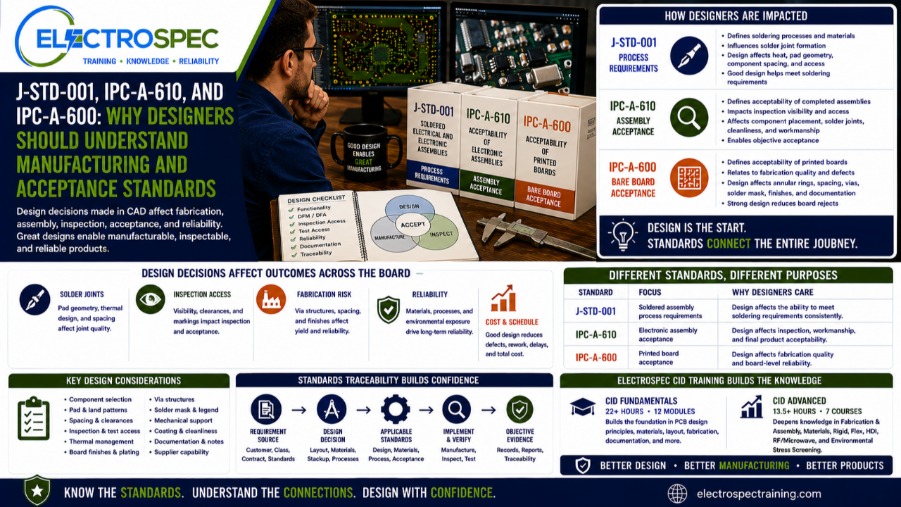
PCB designers are not usually soldering operators.
They are not usually final inspectors.
They are not usually incoming bare board inspectors.
But their design decisions affect all of those functions.
That is why PCB designers should understand manufacturing and acceptance standards, even when those standards are not design standards.
Three of the most important examples are J-STD-001, IPC-A-610, and IPC-A-600.
These standards support different parts of the electronics manufacturing and acceptance process.
J-STD-001 addresses requirements for soldered electrical and electronic assemblies.
IPC-A-610 addresses acceptability of electronic assemblies.
IPC-A-600 addresses acceptability of printed boards.
Designers may not perform those operations directly, but they influence whether the product can meet those requirements.
That is the key point.
Designers Influence Manufacturing Before Manufacturing Begins
Manufacturing problems often begin before the product reaches the factory.
They begin in design.
A land pattern choice can affect solder joint formation.
A thermal relief decision can affect solder flow.
A component spacing decision can affect assembly access.
A package selection can affect inspection method.
A board finish decision can affect solderability.
A test point decision can affect verification.
A dense layout can affect cleaning, coating, and rework.
A documentation decision can affect supplier interpretation.
By the time the product reaches manufacturing, many process risks have already been built into the design.
That is why designers need awareness of manufacturing and acceptance standards.
J-STD-001: Process Requirements Designers Should Respect
J-STD-001 is commonly associated with soldered electrical and electronic assemblies.
It is a process and workmanship requirement standard, not a PCB layout design standard.
That does not mean designers can ignore it.
Designers influence whether the assembly process has a fair chance of meeting soldering requirements.
Design choices can affect:
- solder joint geometry
- land pattern suitability
- thermal mass
- hole-to-lead relationship
- lead protrusion
- solder fill
- component mounting
- cleanliness
- coating compatibility
- rework access
- material compatibility
- solderability
- process control
A soldering operator may form the joint, but the designer helps determine whether that joint can be formed reliably.
Poor design can make good workmanship difficult.
Good design supports good workmanship.
IPC-A-610: Acceptance Criteria Designers Should Understand
IPC-A-610 is commonly used for the acceptability of completed electronic assemblies.
Designers may not be final inspectors, but designers should understand how the product will be judged.
IPC-A-610 awareness helps designers think about:
- component mounting
- solder joint appearance
- alignment
- spacing
- cleanliness
- damage
- hardware installation
- marking visibility
- polarity indicators
- connector installation
- wire and terminal interfaces
- coating conditions
- workmanship conditions
A design that blocks visual access, hides markings, prevents clear inspection, or creates marginal solder joint geometry may become difficult to accept with confidence.
That does not mean designers must become inspectors.
It means designers should understand how inspection and acceptance work downstream.
IPC-A-600: Bare Board Acceptability Starts with Design
IPC-A-600 addresses printed board acceptability.
This matters because the bare board is the foundation for the assembly.
A designer may not inspect bare boards at receiving inspection, but the designer’s choices influence bare board quality and fabrication risk.
Design choices can affect:
- conductor width and spacing
- annular ring
- hole quality
- plating reliability
- via structures
- solder mask registration
- board thickness
- bow and twist
- surface finish
- laminate integrity
- marking
- documentation clarity
- supplier capability
A fabricated board that fails acceptability expectations can delay assembly before the first component is placed.
Designers should understand the types of fabrication issues that can appear later as incoming inspection findings, assembly defects, or reliability problems.
These Standards Are Not the Same
A common mistake is to treat all IPC standards as if they do the same thing.
They do not.
Each standard serves a different purpose.
| Standard | Primary Role | Why Designers Should Care |
|---|---|---|
| J-STD-001 | Soldered assembly requirements | Design affects whether soldering requirements can be met |
| IPC-A-610 | Electronic assembly acceptability | Design affects whether the final product can be inspected and accepted |
| IPC-A-600 | Printed board acceptability | Design affects whether the bare board can be fabricated and accepted |
Designers need to understand the difference.
A design requirement is not the same as a process requirement.
A process requirement is not the same as an acceptance criterion.
An acceptance criterion is not the same as proof that the design is reliable.
But all of these pieces connect.
Design Decisions Affect Solder Joint Reliability
Solder joint reliability is often judged at the end of manufacturing, but many solder joint risks are created earlier.
Designers influence solder joint reliability through:
- pad geometry
- component termination selection
- hole size
- lead fit
- thermal relief
- copper balance
- component spacing
- board finish
- package selection
- board thickness
- assembly process compatibility
- mechanical support
- vibration exposure
- thermal cycling exposure
A solder joint is not only a manufacturing result.
It is also a design outcome.
Manufacturing forms the joint.
Design sets many of the conditions for success.
Designers Should Understand Inspection Access
Inspection access is one of the easiest design issues to overlook.
A designer may place components to optimize electrical performance, density, or routing efficiency.
But the organization still needs to inspect and accept the product.
Designers should ask:
- Can the solder joints be seen?
- If they cannot be seen, what alternate inspection method is planned?
- Are polarity marks visible after assembly?
- Are reference designators visible where needed?
- Are connectors and hardware accessible?
- Can coating be inspected?
- Can cleanliness be verified?
- Can test points be reached?
- Can bottom termination components be verified?
- Can rework be performed if allowed?
If the answer is unclear, the design review is not complete.
Inspection strategy should not be discovered at final inspection.
Designers Should Understand Fabrication Acceptance
The fabricated printed board must support assembly and reliability.
Designers should think about fabrication acceptance before release.
Important questions include:
- Can the supplier build the stackup reliably?
- Are conductor widths and spacings appropriate?
- Are via structures within supplier capability?
- Are annular ring requirements realistic?
- Are fabrication notes clear?
- Are solder mask clearances appropriate?
- Is the surface finish suitable for the assembly process?
- Are tolerances properly defined?
- Are special requirements flowed down?
- Are inspection and acceptance expectations clear?
IPC-A-600 awareness helps designers understand what the bare board must satisfy before assembly begins.
Designers Should Understand Process Capability
Standards define requirements, but process capability determines whether those requirements can be met consistently.
A design may technically meet a design rule but still be difficult to build.
Designers should understand the relationship between:
- design intent
- fabrication capability
- assembly process capability
- inspection capability
- test capability
- supplier capability
- product class
- customer requirements
- reliability expectations
This is where manufacturing-aware design becomes critical.
A designer who understands process capability can reduce supplier questions, rework, delays, and acceptance problems.
Designers Do Not Need Every Operator Certification
This is important.
Designers do not need to become certified in every hands-on manufacturing task.
They do not need to perform every soldering operation.
They do not need to inspect every final assembly.
They do not need to become bare board inspectors.
But they do need standards awareness.
They need to understand how their design decisions affect the people who fabricate, assemble, inspect, test, and accept the product.
Training should match the role.
Operators need task-specific training.
Inspectors need acceptance criteria training.
Process engineers need process control knowledge.
Designers need standards-based design understanding that connects design choices to real manufacturing and acceptance outcomes.
CID and CID Advanced Help Build That Connection
ElectroSpec’s CID Fundamentals course helps designers build the foundation.
It includes 22+ hours of on-demand training across 12 structured modules covering materials, layout principles, mechanical and electrical considerations, thermal management, component technologies, interconnections, fabrication requirements, documentation, quality assurance, manufacturability, and standards-based design thinking.
ElectroSpec CID Advanced expands into:
- PCB Fabrication & Assembly
- PCB Materials
- Rigid PCB Design
- Flexible PCB Design
- HDI PCB Design
- RF/Microwave PCB Design
- Environmental Stress Screening
That matters because designers need to understand how design standards connect to manufacturing and acceptance standards.
A strong designer does not work in isolation from fabrication, assembly, inspection, and quality.
Standards Traceability Matters
When a design decision is questioned, the designer should know where the decision came from.
Was it based on a design standard?
A material requirement?
A fabrication limit?
A soldering requirement?
An assembly acceptance criterion?
A bare board acceptability concern?
A customer drawing?
A Class 3 requirement?
A qualification requirement?
A supplier capability?
Engineering judgment?
Traceability helps the designer communicate clearly.
It also helps the organization prove conformance with objective evidence.
A design decision without traceability can become an opinion.
A design decision with traceability becomes part of the engineering record.
The Drawing Note Is Not Enough
Simply calling out a standard on a drawing does not guarantee success.
A drawing note may invoke requirements, but the design still has to support those requirements.
For example:
A drawing may invoke Class 3 expectations, but the design may still create poor inspection access.
A drawing may invoke soldering requirements, but the pad geometry may still make solder joint formation difficult.
A drawing may invoke bare board requirements, but the via structure may still exceed supplier capability.
A drawing may invoke coating requirements, but the layout may not support masking, coverage, or inspection.
The drawing note is only part of the requirement system.
The design must make compliance possible.
Manufacturing Feedback Should Return to Design
Manufacturing and inspection feedback should not stop at production.
It should return to design.
Useful feedback includes:
- repeated solder defects
- poor through-hole fill
- insufficient solder paste transfer
- solder bridging
- tombstoning
- component misalignment
- solder mask issues
- bare board defects
- inspection access problems
- hidden markings
- difficult rework
- cleaning problems
- coating issues
- test access problems
- qualification failures
This feedback helps designers improve future products.
A design organization becomes stronger when manufacturing and inspection findings are used as design lessons.
Designers Should Talk to Process and Inspection Teams Early
The best time to discuss manufacturing and acceptance standards is before release.
Design reviews should include people who understand:
- fabrication
- assembly
- soldering
- inspection
- test
- quality
- reliability
- supplier capability
- customer requirements
A cross-functional review can catch problems early.
It can prevent a design from being released with avoidable manufacturing, inspection, or acceptance risks.
A good design review asks not only, “Does the circuit work?”
It also asks, “Can we build it, inspect it, accept it, and trust it?”
Independently Developed by ElectroSpec
ElectroSpec’s CID and CID Advanced courses are independently developed by ElectroSpec.
They are not IPC-authorized training and they are not official IPC curriculum.
ElectroSpec developed these courses to provide practical, standards-connected, manufacturing-aware design training for students preparing for CID and CID+ certification.
The focus is not only on knowing standard names.
The focus is on understanding how design decisions affect fabrication, assembly, inspection, acceptance, reliability, and customer confidence.
Final Thought
Designers do not need to be operators.
They do not need to be inspectors.
But they do need to understand how manufacturing and acceptance standards affect the products they design.
J-STD-001 helps designers understand soldered assembly requirements.
IPC-A-610 helps designers understand completed assembly acceptability.
IPC-A-600 helps designers understand printed board acceptability.
Together, these standards remind designers that PCB design does not end at layout release.
A good design can be fabricated.
A good design can be assembled.
A good design can be inspected.
A good design can be accepted.
A good design can be trusted.
Related ElectroSpec Training
ElectroSpec’s CID Fundamentals course provides 22+ hours of on-demand PCB design training across 12 structured modules.
ElectroSpec’s CID Advanced training expands into PCB Fabrication & Assembly, PCB Materials, Rigid PCB Design, Flexible PCB Design, HDI PCB Design, RF/Microwave PCB Design, and Environmental Stress Screening.
Together, these courses help designers build the standards-connected foundation needed for CID and CID+ certification preparation.
Coming Next
Aerospace and Defense Are Not Requirements: Standards Define the Real Design Obligation
In the next article, we will discuss why market labels such as aerospace, defense, space, and high reliability must be translated into real requirements, such as Class 3 expectations, customer flow-downs, NASA, ESA, military specifications, environmental qualification, and objective evidence.
IPC CID Certification — ElectroSpec
IPC CID+ Certification — ElectroSpec
IPC CID/CID+ Bundle — Complete PCB Design Certification — ElectroSpec