Rigid, Flex, RF, and HDI: Why One PCB Design Standard Is Not Enough
Aug 16, 2026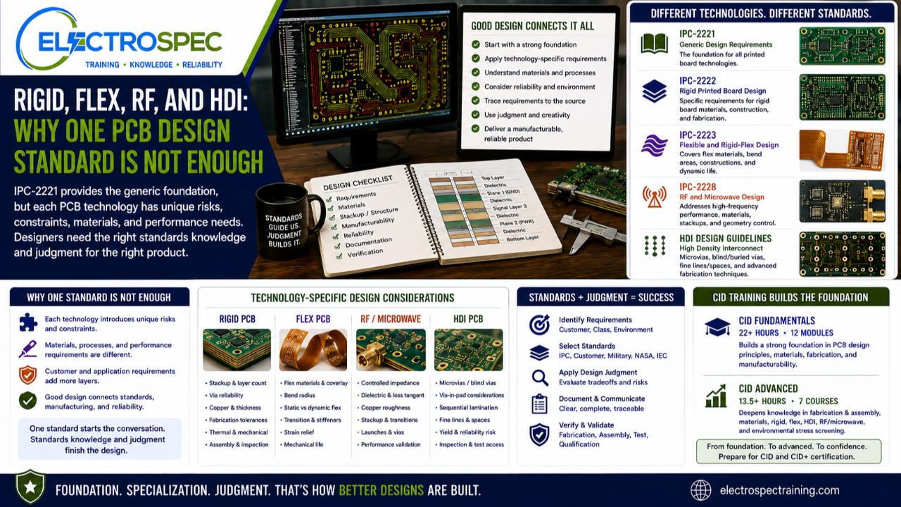
IPC-2221 is an essential starting point for PCB design.
It gives designers the generic foundation. It helps establish design language, basic requirements, spacing logic, material considerations, documentation expectations, and the framework needed to think about printed board design.
But PCB design does not stop at the generic foundation.
A rigid board is not the same as a flex circuit.
A flex circuit is not the same as a rigid-flex assembly.
An RF or microwave board is not the same as a conventional digital board.
An HDI design is not the same as a traditional through-hole or standard multilayer design.
Each technology adds its own risks, constraints, materials, fabrication methods, inspection concerns, and reliability expectations.
That is why one design standard is not enough.
IPC-2221 Starts the Conversation
IPC-2221 helps designers understand the broad design framework.
It supports foundational thinking about:
materials
spacing
conductors
board construction
mechanical design
electrical design
thermal considerations
documentation
manufacturing considerations
quality expectations
That foundation matters.
A designer who does not understand the generic design framework will struggle when the design becomes more specialized.
However, generic design requirements are only the beginning.
The designer still has to ask, “What type of board am I designing, what technology applies, what environment will it see, and what additional requirements must be considered?”
Rigid Boards Have Their Own Design Concerns
Rigid PCB design may look familiar, but it still requires specific design knowledge.
Rigid boards involve decisions about stackup, layer count, copper thickness, plated through-holes, annular ring, solder mask, surface finish, board thickness, mechanical support, panelization, fabrication tolerances, and assembly compatibility.
Rigid PCB design often connects to IPC-2222, which focuses on rigid printed board design.
That matters because rigid boards have construction and fabrication concerns that go beyond the generic starting point.
A designer must understand how choices affect:
fabrication yield
plating reliability
solderability
mechanical strength
thermal performance
assembly process capability
inspection and test
product reliability
Rigid does not mean simple.
A high-layer-count rigid board, high-current board, high-reliability Class 3 board, or harsh-environment product can become technically demanding very quickly.
Flex and Rigid-Flex Designs Add Mechanical Life
Flex and rigid-flex designs introduce a different design problem.
The board may bend, fold, move, flex during installation, or flex repeatedly during use.
That means the designer must think about mechanical life, not only electrical connection.
Flex and rigid-flex design connects to IPC-2223, which focuses on flexible and rigid-flex printed board design.
Flex design considerations include:
base material
adhesive systems
adhesiveless constructions
copper type
coverlay
bend radius
static versus dynamic flexing
conductor routing through bend areas
stiffeners
strain relief
transition zones
connector support
fabrication tolerances
assembly handling
inspection access
qualification environment
A flex circuit does not succeed because it can bend.
It succeeds because the designer understands materials, motion, stress, fabrication, assembly, and reliability.
RF and Microwave Boards Change the Electrical Problem
RF, microwave, and high-frequency designs require a different level of material and geometry control.
At higher frequencies, the printed board becomes part of the electrical performance of the system.
Trace geometry, copper roughness, dielectric constant, loss tangent, surface finish, stackup, via transitions, reference planes, connectors, launches, and fabrication tolerance all matter.
RF and microwave design connects to IPC-2228, which focuses on RF and microwave printed board design.
Designers must consider:
controlled impedance
dielectric materials
loss characteristics
copper roughness
layer transitions
return paths
via structures
grounding strategy
connector launches
routing geometry
fabrication tolerance
test and validation
RF performance is not only routed into the board.
It is built into the materials, stackup, geometry, fabrication process, and verification strategy.
HDI Requires More Than Dense Layout
HDI design is often treated as a density problem.
It is more than that.
HDI may involve microvias, blind vias, buried vias, via-in-pad, sequential lamination, fine lines and spaces, advanced materials, tight tolerances, dense component packaging, and more complex inspection and test strategies.
HDI requires careful attention to fabrication capability and reliability.
Designers must think about:
microvia structures
stacked or staggered vias
via filling and plating
sequential lamination
material stability
registration tolerance
yield risk
thermal cycling
interconnect reliability
inspection and test access
supplier capability
customer requirements
HDI is also an area where designers must be especially careful because technology and fabrication capability continue to evolve.
A designer should not assume that one generic standard or one historical reference answers every HDI question.
HDI design must be connected to current requirements, supplier capability, customer expectations, qualification needs, and engineering judgment.
Technology-Specific Standards Help Control Technology-Specific Risk
The reason specific standards exist is simple.
Different technologies create different risks.
Rigid board risk is not identical to flex board risk.
Flex board risk is not identical to RF risk.
RF risk is not identical to HDI risk.
Each technology changes the design problem.
A generic foundation helps the designer ask the first questions.
Technology-specific knowledge helps the designer ask the right next questions.
That is why strong designers need both.
They need the foundation, and they need the specialized design framework.
Standards Still Require Judgment
Even when a technology-specific standard applies, the designer still has to use judgment.
A standard may define requirements, constraints, recommendations, and expectations.
But the designer still has to decide:
What is the product used for?
What class applies?
What customer requirements apply?
What environment will the product see?
What supplier capability is available?
What fabrication process will be used?
What assembly process will be used?
How will the product be inspected?
How will the product be tested?
How will reliability be demonstrated?
Standards define the requirements framework.
Designers create the product within that framework.
CID Builds the Generic Foundation
ElectroSpec’s CID Fundamentals course helps students build the design foundation.
The course includes 22+ hours of on-demand PCB fundamentals training across 12 structured modules.
It covers materials, layout principles, mechanical and electrical considerations, thermal management, component technologies, interconnections, fabrication requirements, documentation, quality assurance, manufacturability, and standards-based design thinking.
That foundation is critical because every advanced design still depends on the basics.
Rigid, flex, RF, and HDI designs all require the designer to understand materials, fabrication, documentation, quality, and manufacturing impact.
CID Advanced Builds the Specialized Framework
ElectroSpec CID Advanced expands into advanced design domains that build on the foundation.
The advanced track includes:
PCB Fabrication & Assembly
PCB Materials
Rigid PCB Design
Flexible PCB Design
HDI PCB Design
RF/Microwave PCB Design
Environmental Stress Screening
These topics were selected because advanced PCB design is not one subject.
It is a connected set of design problems.
A designer working toward CID+ level knowledge needs to understand how materials, fabrication, technology type, environmental stress, and reliability interact.
That is the purpose of CID Advanced.
Standards Traceability Becomes More Important as Designs Become More Advanced
As design complexity increases, traceability becomes more important.
A designer should know where a requirement comes from and why it matters.
For example:
A rigid board requirement may connect to rigid board design guidance and fabrication capability.
A flex bend requirement may connect to flex materials, construction, and mechanical use.
An RF stackup requirement may connect to impedance, material properties, and fabrication tolerances.
An HDI via structure may connect to supplier capability, reliability risk, and qualification requirements.
A high-reliability requirement may connect to Class 3 expectations, customer flow-downs, NASA, ESA, military, medical, or harsh-environment requirements.
The designer must be able to trace design decisions back to the correct source.
That is how design decisions become defensible.
Customer Requirements May Add Another Layer
IPC standards are important, but customer requirements may add more.
A customer drawing, contract, purchase order, system specification, qualification plan, or program requirement may impose additional obligations.
For advanced products, designers may also encounter:
Class 3 requirements
NASA requirements
ESA requirements
military specifications
IEC requirements
medical product requirements
company design rules
supplier requirements
environmental qualification requirements
material restrictions
documentation and traceability requirements
The designer must understand the full requirement flow-down.
A standard may provide the foundation.
The customer requirement defines the actual obligation.
One Standard Cannot Carry the Whole Design
A single standard cannot fully address every board technology, product class, customer expectation, material concern, fabrication process, inspection need, and qualification environment.
That is why designers need standards literacy.
They must understand how to begin with the generic foundation, then move into the specific requirements that apply to the product.
For many designs, that means starting with IPC-2221, then moving into more specific rigid, flex, RF, HDI, material, fabrication, assembly, inspection, and reliability considerations.
The stronger designer does not ask, “What one standard answers everything?”
The stronger designer asks, “What full requirement set applies to this product?”
Independently Developed by ElectroSpec
ElectroSpec’s CID and CID Advanced courses are independently developed by ElectroSpec.
They are not IPC-authorized training and they are not official IPC curriculum.
ElectroSpec developed these courses to provide practical, standards-connected, manufacturing-aware design training for students preparing for CID and CID+ certification.
The focus is not only on knowing standard numbers.
The focus is on understanding how requirements, materials, fabrication, manufacturing, inspection, reliability, and design judgment connect in real products.
Final Thought
IPC-2221 provides the foundation.
But advanced PCB design requires more than one foundation standard.
Rigid boards, flex circuits, rigid-flex assemblies, RF and microwave boards, HDI designs, and harsh-environment products each introduce different risks and requirements.
The designer must know when the generic foundation is enough and when more specific knowledge is required.
That is the heart of standards-based design judgment.
One standard may start the conversation.
A strong designer knows how to finish it.
Related ElectroSpec Training
ElectroSpec’s CID Fundamentals course provides 22+ hours of on-demand PCB design training across 12 structured modules.
ElectroSpec’s CID Advanced training expands into PCB Fabrication & Assembly, PCB Materials, Rigid PCB Design, Flexible PCB Design, HDI PCB Design, RF/Microwave PCB Design, and Environmental Stress Screening.
Together, these courses help designers build the foundation and advanced standards awareness needed for CID and CID+ certification preparation.
Coming Next
The Supporting Standards Designers Cannot Ignore
In the next article, we will discuss why PCB designers must understand supporting standards for materials, solder mask, copper foil, laminates, solderability, conformal coating, assembly, inspection, and quality.
IPC CID Certification — ElectroSpec
IPC CID+ Certification — ElectroSpec
IPC CID/CID+ Bundle — Complete PCB Design Certification — ElectroSpec