Standards Traceability: The Missing Skill in PCB Design Training
Aug 24, 2026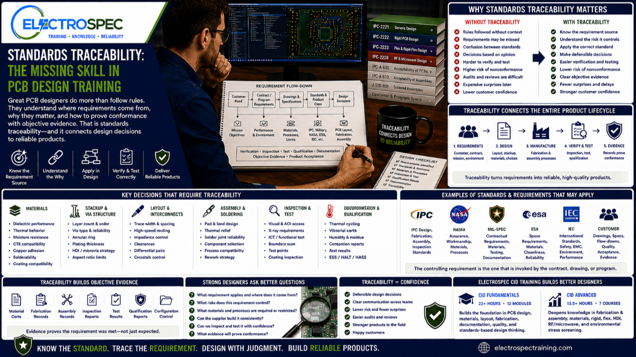
PCB design training often focuses on rules.
Trace width.
Spacing.
Vias.
Stackup.
Materials.
Component placement.
Routing.
Documentation.
Those topics are important.
But there is another skill that separates a stronger designer from someone who simply follows instructions.
That skill is standards traceability.
Standards traceability means the designer understands where a requirement comes from, why it matters, how it affects the product, and how it can be verified later.
A designer should not only know what rule to follow.
A designer should know the source of the rule, the risk it controls, the standard or customer requirement behind it, and the objective evidence needed to prove the product meets the requirement.
That is where real design maturity begins.
A Rule Without Traceability Is Just a Number
Many designers learn rules as numbers.
Use this spacing.
Use this trace width.
Use this annular ring.
Use this material.
Use this via structure.
Use this solder mask clearance.
But a number without context can be dangerous.
The designer should ask:
- Where did this value come from?
- Is it from a standard?
- Is it from a customer drawing?
- Is it from a supplier capability table?
- Is it from Class 3 requirements?
- Is it from a voltage or current requirement?
- Is it from a reliability concern?
- Is it from a qualification plan?
- Is it from company best practice?
- Is it engineering judgment?
Those answers matter.
A supplier preference is not the same as a customer requirement.
A company guideline is not the same as a contractual flow-down.
A design rule is not always the same as a fabrication capability limit.
A standard requirement is not always the same as a best practice recommendation.
Traceability helps the designer understand the difference.
PCB Design Is a Requirement Flow-Down Problem
A PCB does not exist in isolation.
It exists inside a product, a customer need, a contract, a drawing, a standard, a manufacturing process, and a reliability expectation.
A typical requirement flow may look like this:
Customer need leads to product requirements.
Product requirements lead to drawings and specifications.
Drawings and specifications invoke standards, classes, materials, and performance expectations.
Those requirements affect PCB layout, fabrication, assembly, inspection, test, and qualification.
Inspection, test, and records become objective evidence.
That is the path from requirement to product acceptance.
If the designer does not understand that path, important requirements may be missed.
Standards Traceability Connects Design to Manufacturing
Designers make decisions before manufacturing begins.
Those decisions affect whether the product can be fabricated, assembled, inspected, tested, and accepted.
For example:
A material decision affects fabrication, soldering, thermal performance, moisture behavior, and reliability.
A via decision affects fabrication capability, plating reliability, inspection, and long-term performance.
A pad decision affects solder joint formation, inspection, and rework.
A spacing decision affects electrical performance, manufacturability, cleanliness, coating, and reliability.
A documentation decision affects supplier interpretation, inspection, and objective evidence.
Traceability connects those decisions back to the requirement source.
That is how designers move from “I chose this because it seemed right” to “I chose this because the requirement, standard, environment, and manufacturing process support this decision.”
Standards Traceability Supports Better Design Reviews
A good design review should not only ask whether the circuit works.
It should ask whether the design is traceable.
Key questions include:
- What standards are invoked?
- What revision levels apply?
- What product class applies?
- What customer requirements are flowed down?
- What materials are specified?
- What fabrication requirements apply?
- What assembly requirements apply?
- What inspection and test evidence is required?
- What qualification environment applies?
- What risks were considered?
- What decisions need documentation?
These questions help prevent late surprises.
They also help designers communicate more clearly with process engineers, fabricators, assemblers, inspectors, quality teams, and customers.
Traceability Helps Prevent “Standards Confusion”
Many design problems happen because people use standards language loosely.
Someone may say, “Build it to IPC.”
But what does that mean?
IPC design requirements?
Bare board acceptability?
Assembly acceptability?
Soldering process requirements?
Class 2?
Class 3?
Space Addendum?
Customer-specific flow-downs?
Aerospace requirement?
Defense contract requirement?
IPC is not one requirement.
It is a standards ecosystem.
The designer must know which standard applies, what role it plays, and how it connects to the product.
That is standards traceability.
One Standard Rarely Tells the Whole Story
A PCB designer may begin with a foundational design standard, but real products often require more.
The final requirement set may include:
- generic design requirements
- rigid board requirements
- flex or rigid-flex requirements
- RF or microwave design requirements
- material specifications
- bare board acceptability requirements
- soldered assembly requirements
- finished assembly acceptability criteria
- solderability requirements
- conformal coating requirements
- cleanliness requirements
- customer drawings
- military specifications
- NASA requirements
- ESA requirements
- IEC requirements
- environmental qualification plans
A designer does not need to memorize every standard.
But a designer must understand that standards connect.
The stronger designer knows how to follow the requirement trail.
Traceability Builds Objective Evidence
High-reliability electronics require more than good intentions.
They require evidence.
Objective evidence may include:
- approved drawings
- material certifications
- fabrication records
- assembly records
- inspection reports
- test results
- qualification reports
- process control records
- configuration control records
- traceability records
- nonconformance records
- deviation approvals
Standards traceability helps connect those records to the requirement.
The requirement defines what must be met.
The design implements the requirement.
Manufacturing builds to the requirement.
Inspection and test verify the requirement.
Records prove the requirement was met.
That is why traceability matters.
CID Builds the Foundation for Traceability
ElectroSpec’s CID Fundamentals course is designed to help students build the standards-based foundation needed for PCB design.
The course includes 22+ hours of on-demand PCB design training across 12 structured modules covering materials, layout principles, mechanical and electrical considerations, thermal management, component technologies, interconnections, fabrication requirements, documentation, quality assurance, manufacturability, and standards-based design thinking.
That foundation helps designers understand how decisions connect.
The goal is not simply to memorize design rules.
The goal is to help designers understand where requirements come from, how they affect the product, and how to apply them in real design work.
CID Advanced Builds the Larger Standards Framework
ElectroSpec CID Advanced expands the traceability discussion into advanced design areas.
The advanced track includes:
- PCB Fabrication & Assembly
- PCB Materials
- Rigid PCB Design
- Flexible PCB Design
- HDI PCB Design
- RF/Microwave PCB Design
- Environmental Stress Screening
These topics are deeply connected to traceability.
A flex design decision may trace to material selection, bend requirements, fabrication capability, and reliability.
An HDI decision may trace to microvia structure, supplier capability, plating reliability, and qualification risk.
An RF decision may trace to stackup, dielectric material, impedance control, copper properties, and test requirements.
An environmental stress decision may trace to shock, vibration, humidity, thermal cycling, qualification, and objective evidence.
Advanced PCB design requires more than knowing what standards exist.
It requires knowing how to connect them.
Traceability Helps Designers Defend Their Decisions
Design decisions are often questioned later.
A supplier may ask why a requirement was specified.
A customer may ask how a requirement was met.
An inspector may question acceptability.
A quality engineer may need objective evidence.
A failure analysis team may investigate a field issue.
An auditor may ask for the requirement basis.
When that happens, traceability protects the design team.
A traceable decision is easier to explain.
A traceable decision is easier to verify.
A traceable decision is easier to defend.
A design decision without traceability may become opinion.
A design decision with traceability becomes part of the engineering record.
Traceability Does Not Replace Judgment
Traceability is not a substitute for engineering judgment.
It supports judgment.
Standards may define requirements, but designers still need to make decisions.
They must balance:
- performance
- manufacturability
- reliability
- inspection access
- testability
- cost
- schedule
- material availability
- supplier capability
- customer requirements
- qualification risk
Traceability helps the designer understand the basis for those decisions.
Judgment helps the designer choose the right solution.
Both are needed.
Designers Need More Than Course Completion
A short course may teach a topic.
A certificate of completion may show that a course was completed.
But designers need a durable reference framework.
They need to understand how standards, requirements, materials, fabrication, assembly, inspection, test, qualification, and documentation connect.
That is why ElectroSpec emphasizes CID and CID Advanced as standards-connected certification preparation pathways.
The goal is not just to finish training.
The goal is to build better designers.
Independently Developed by ElectroSpec
ElectroSpec’s CID and CID Advanced courses are independently developed by ElectroSpec.
They are not IPC-authorized training and they are not official IPC curriculum.
ElectroSpec developed these courses to provide practical, standards-connected, manufacturing-aware design training for students preparing for CID and CID+ certification.
The focus is not simply on knowing standards names.
The focus is on understanding how requirements become reliable products.
Final Thought
Standards traceability may be one of the most important skills missing from basic PCB design training.
It teaches designers to ask better questions.
Where did this requirement come from?
Why does it matter?
How does it affect the product?
How will it be verified?
What evidence will prove conformance?
A designer who can answer those questions is not just following rules.
That designer is practicing engineering.
PCB design is not only about creating the layout.
It is about creating a product that can be built, inspected, tested, accepted, documented, and trusted.
Traceability is what connects the design to that outcome.
Related ElectroSpec Training
ElectroSpec’s CID Fundamentals course provides 22+ hours of on-demand PCB design training across 12 structured modules.
ElectroSpec’s CID Advanced training expands into PCB Fabrication & Assembly, PCB Materials, Rigid PCB Design, Flexible PCB Design, HDI PCB Design, RF/Microwave PCB Design, and Environmental Stress Screening.
Together, these courses help designers build the standards-connected foundation needed for CID and CID+ certification preparation.
Coming Next
From Requirement Flow-Down to PCB Layout
In the next article, we will discuss how customer needs, drawings, standards, product class, materials, fabrication limits, assembly requirements, inspection needs, and qualification plans should flow into real PCB layout decisions.
IPC CID Certification — ElectroSpec
IPC CID+ Certification — ElectroSpec
IPC CID/CID+ Bundle — Complete PCB Design Certification — ElectroSpec